Introduction
Access Control Systems (ACSs) are used by many organizations, whether commercial or non-profit, as a means of providing scalable access to facilities or systems with finer degrees of control and fewer physical management problems than keys. When Triple Cities Makerspace (TCMS) moved into the old Spool Manufacturing building in Johnson City, NY back in 2013, the board wanted to provide members with 24/7 access to the new facilities using RFID tags and a computerized tag management system, as opposed to making use of physical keys which are easy to lose and hard to track.
The first attempt at a homegrown access control project started with a single Arduino Atmega 2560 microcontroller board, a numeric keypad with a built-in RFID reader, and a circuit board of relays for controlling an electronic door lock. TCMS had all of this hardware at hand already, but no software to make the system actually work, and off-the-shelf systems weren’t really an option with the minimal budget available. Two then-new TCMS members, Adam Biener (a software developer / consultant) and Evil Jim Ulrich (an expert in, among many other things, Arduino and analog electronics), volunteered their skillsets to the board to make a fully-functioning access control system from the hardware just described and software created by Adam.
The first step in developing the ACS software was to figure out what TCMS really needed regarding access control capabilities. After thinking for a while and getting feedback from the TCMS board, it was decided that the ACS needed to have:
- An easy way to add, remove, and edit the info of TCMS members
- An easy to way to assign and re-assign RFID tags to a member
- An easy way to enable or disable building access based on membership status, with membership status determined by whether or not the member in question has actually paid their dues
- The ability to restrict access to certain tools that required basic usage and safety training, such as table saws and other large power tools; a member will get access to said tools when they complete the training
Phase 1: Initial Implementation with Door Access
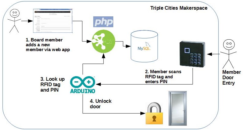
Adam developed a PHP and MySQL-based web app to implement the requirements listed above which, in supplemented form, is still in use by TCMS to the present day. This app allows users to be added to the ACS, integrates with the TCMS billing system, and includes a way for Evil Jim’s Arduino code to query the user database and control the door lock based on the user-specific information retrieved from this database. The basic architecture of this system is shown in the diagram below:
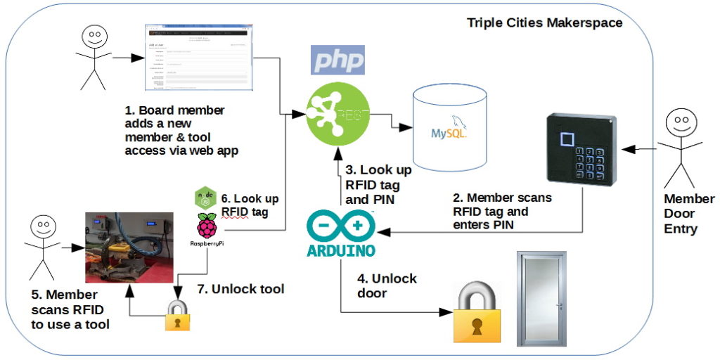
At the center of this system is the MySQL database which maintains the user list, access rules, and some other settings. The web app allows a TCMS administrator (typically board members) to maintain and update this information. There is also a REST API layer that allows other devices (doors, tools) to authenticate users and enable other types of machine-to-machine communications; since tool access was part of the long term plan for the TCMS facilities, the ACS was designed to accommodate this functionality. A TCMS administrator can define a selection of “devices”, which may include a door or a tool, with each device having a different set of access rules that determines user-specific accessibility. Access to the TCMS main entrance requires a PIN and the scanned RFID tag, but tools only require use of the RFID tag. Finally, automated offsite backups of the ACS data were implemented to allow recovery from catastrophic failure, like a bad hard drive.
Implementing ACS functionality to the TCMS facilities’ main entrance was the highest priority in terms of system deployment, so Adam and Evil Jim started with that; following the usual round of hardware and software testing, the system was implemented on the TCMS front door, and has been in use ever since. Adam performed occasional software updates to make the system more reliable and the web app easier to use, especially on a smartphone, but the core functionality remains unchanged since this first deployment. When TCMS moved to its present facilities at 326 State St in Binghamton in 2015, the ACS proved easy to transplant; the server was physically moved, and the wiring and door lock were installed in the new main entrance. Once installation was completed and the server was powered up, the ACS software booted and worked without any problems.
Phase 2: Tool Access
Once other building renovations on 362 State St. had been completed, the TCMS board – which now included Adam as secretary – started discussing implementation of the ACS’ tool access functionality for several of the larger, more complex, and/or potentially physically dangerous tools in the TCMS facilities. As there are some security and user interaction considerations for tools which are not applicable to the door, a series of discussions were held to determine requirements for this system. The final requirements are as follows:
- As the tool’s user has already entered their PIN on the main entrance keypad, there shall be no need to enter it again; the tool’s local access hardware is activated by scanning the user’s RFID tag
- The system must check that the user is authorized to make use of the tool by accessing the user’s training information in the ACS via the scanned RFID tag; if the user is authorized, the tool may be turned on
- When the user has finished making use of the tool, they must either press a “reset” button to lock the tool again or it must automatically reset and lock itself again after a period of inactivity; reducing the amount of effort needed to make use of the tool and the tool access hardware is crucial to having both items work well
These requirements, in turn, raised additional questions:
- How can these rules be enforced by the hardware as well as the software?
- How is “inactivity” determined for a given tool?
- How many tools should be secured this way?
- Is there an off-the-shelf set of hardware that could be used? If so, would it work with the current door access control system?
Informal discussions with other Makerspaces were held by Adam to get outside perspective on design principles and implementations as part of this process. As with the original ACS, it was decided in the end to make use of off-the-shelf hardware for the physical component of the tool access functionality for reasons of budget, easy maintenance, and the ability to specifically design a system to fit the somewhat unique needs of a Makerspace. A short list of tools to be controlled with the tool access functionality was decided upon, and as all of these tools had been semi-permanently placed throughout the new TCMS facilities by this point, it was also decided to install the tool access hardware for each tool on the closest wall to the tool for the sake of maximizing space efficiency without resulting in potential usage hazards.
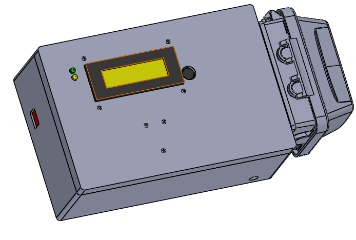
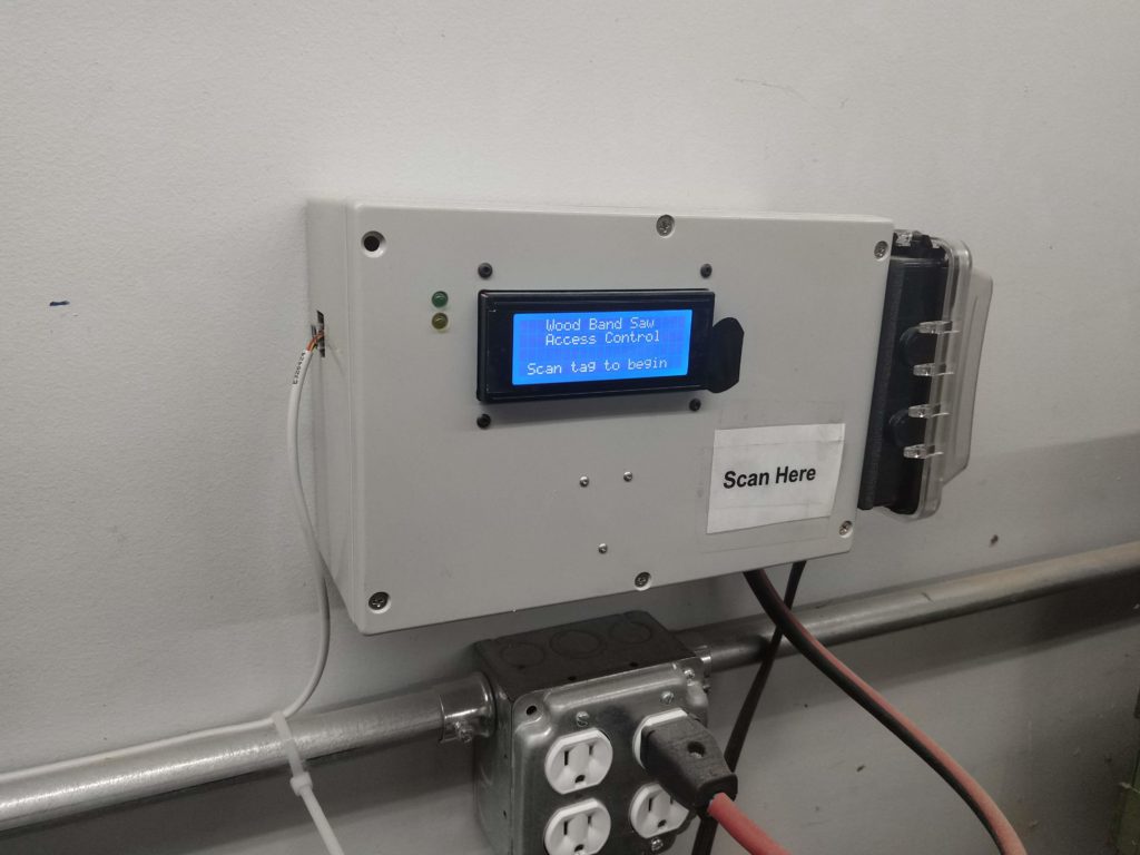
It was also decided during the design process for the tool access hardware to have screens on each hardware box, to display the status of the ACS with respect to the tool attached to that box. The amount of information displayed on the screen was deliberately kept minimal, for the sake of reducing user distraction while the tool is active. Built-in diagnostics for the tool access hardware is accessible only by specific users designated by the TCMS board, and includes general systems status and debugging info such as current draw (which is used to determine system inactivity).
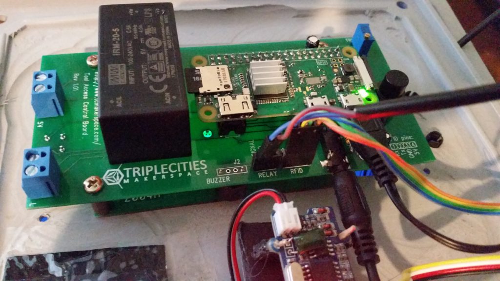
The core of the tool access hardware is a Raspberry Pi Zero W, chosen because it offers the hardware resources necessary to implement the ACS functionality with respect to I/O ports and processing power at a price and power consumption level affordable by the Makerspace. The rest of the hardware was sourced as off-the-shelf components from suppliers such as AliExpress, Amazon, and DigiKey: LCD screens, RFID readers, Meanwell AC-to-DC power supplies to supply power to the tool access hardware, solid state relays and current clamps to control power to the associated tools, and some miscellaneous small electronics components.
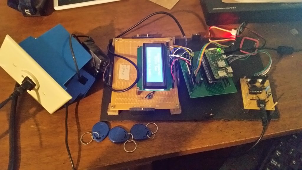
The tool access hardware was designed to remove power from the associated tool(s) altogether when the tool was inactive, to prevent any potential attempts at bypassing the ACS software to access the tool(s). Adam built a custom circuit to read the analog current value from the clamp and convert that current value to a voltage, before digitizing it to a value within a range of 210 and feeding that value to the Pi via an SPI connection. The software implemented on the Pi checks that digitized current draw value against a predefined, tool-specific threshold, and if that value drops below the given threshold, the software disables AC power to the associated tool after a timed delay to ensure that the tool has entered an appropriate state of inactivity. The solid state relays are used to enable AC power to the associated tool once the ACS has verified that the user has had training with that particular tool.
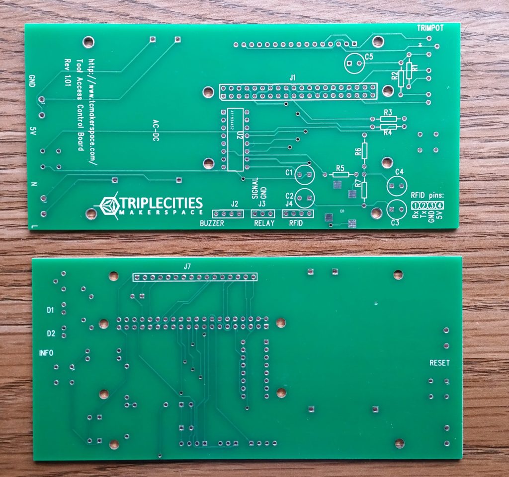
Adam enlisted the help of two other TCMS members in the tool access system’s design process: San Nguyen to design and oversee the manufacturing of the PCBs for the tool access hardware’s custom circuitry, and Cliff Burger to design and fabricate the physical enclosures for the tool access hardware. San has worked in different capacities as a software and electrical engineer, but his background is in PCB design and fabrication, so designing and instigating the manufacturing of a relatively simple PCB layout based on Adam’s circuits and incorporating the Pi and other hardware listed above was easy for him. As is usual for such projects, it took a couple of design revisions following initial debugging to settle on a layout that worked well for the project, but the end product works well! The final PCB has the LCD screen in its center, with other components (the Pi, two LEDs, a reset button, the current-clamp circuitry, etc.) mounted on the PCB with a combination of through-hole and surface-mount techniques.
San used the PCB layout software PADS to create the PCB design on a 2-layer board, as he had experience with that software and could create the design quickly and easily with it. He chose PCBgogo.com to fabricate the boards, as they are able to produce PCBs of reasonable quality inexpensively and with a relatively quick shipping time of ~1 week. A couple of “build parties” were held at the Makerspace to assemble all of the PCBs with their components once the final revisions of the PCBs had arrived; Adam, San, Cliff, and several other board members (Erik Leonard, Samantha Cameron, and John Flinn) all participated in the assembly of these boards.
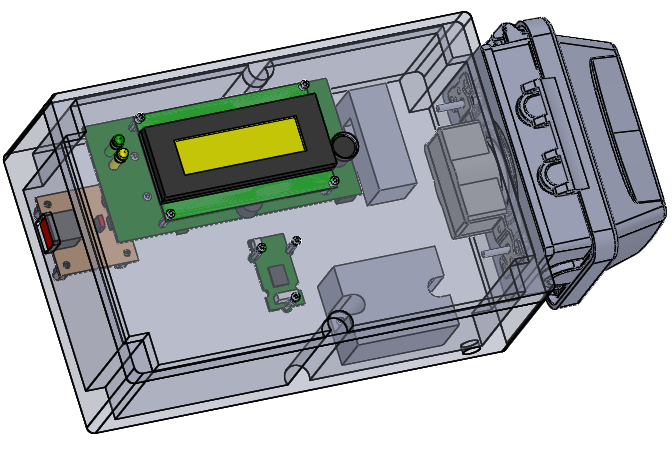
Cliff’s contribution to this project as an experienced machinist and mechanical modeler was to create physical enclosures for the tool access hardware, which he did using a 3D CAD model he’d created in SolidWorks. Like the PCBs, the initial enclosure design required a couple of revisions to finalize following initial testing with the system’s electrical components, but these revisions were minor in nature and followed changes made to the PCB. Cliff chose ABS as the material for the enclosures for reasons of cost, electrical isolation, ease of machining, and ready availability. All of the hardware for the enclosures were chosen from off-the-shelf components readily available from suppliers like McMasterCarr or Fastenal.
Once all of the tool access hardware systems had been fully assembled and had Adam’s software downloaded to the Pis, the systems were wired in with their associated tools, mounted to the walls, and integrated via the Makerspace WiFi network with the ACS. Final testing of the installed systems has proven that they work reliably as intended with minimal intrusion to usage of their associated tools. The total cost per unit of the tool access hardware is estimated to be under $150.
Phases 3 & 4: Dust Collector Integration and Future System Upgrades
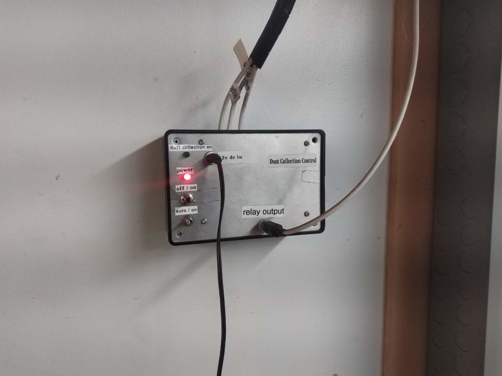
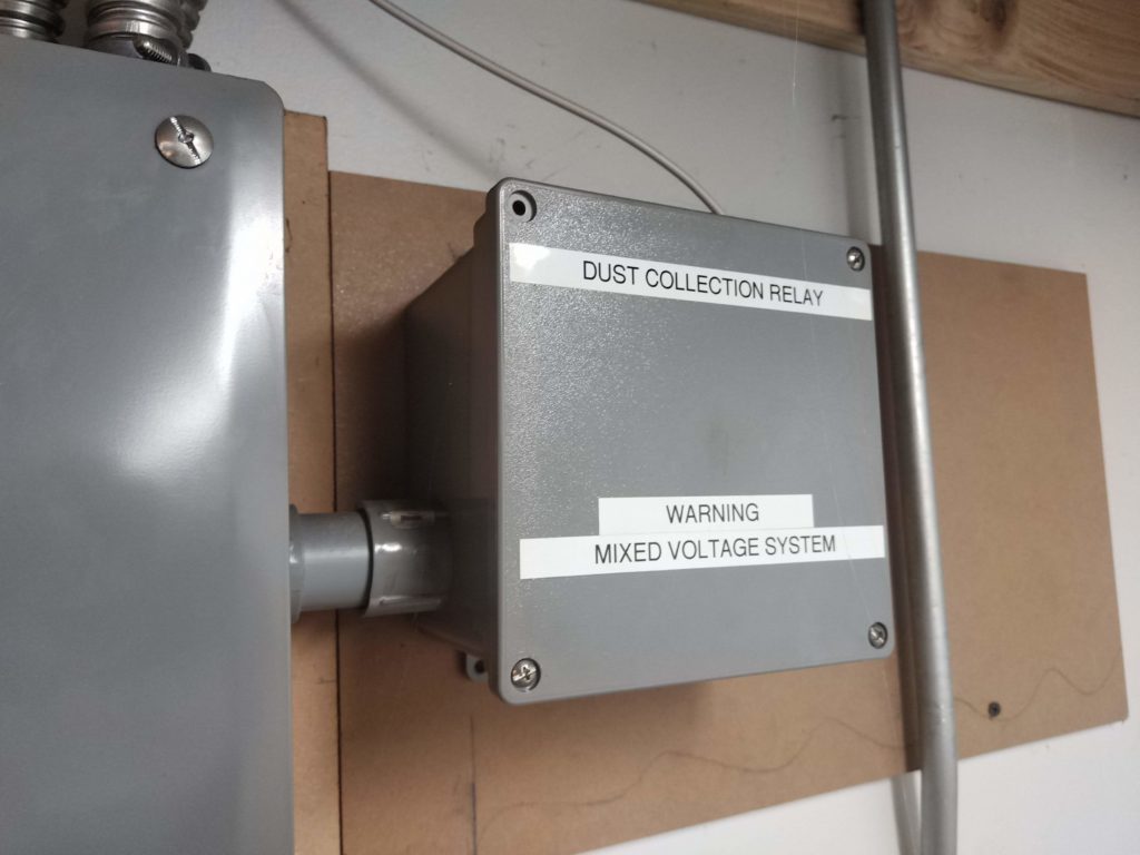
Following the installation of a dust collection system in the TCMS wood shop, Adam decided to integrate it into the ACS / tool access system. He designed and assembled a custom, one-off circuit which is attached to the relay outputs of all ACS boxes associated with specific wood shop tools. When the relay on one of these tools is activated by a user with the appropriate training logged in the ACS, this new circuit sends a signal to a second relay box connected to the dust collector’s power circuitry; the relay box then powers up the dust collector to remove the wood dust from the tool being used. This second relay box powers down the dust collector when the tool being used is deactivated through use of the reset button or when the tool access hardware’s inactivity timer times out.
Phase 4 of this project is intended to facilitate fine-tuning of the ACS and tool access system. One goal is to collect and analyze energy usage reports from each of the tools, via logs of which tools are used and for how long. The end goal here is to create a predictive failure analysis report via pattern analysis of the logged data for each tool, so that the TCMS board can plan for maintenance or replacement of tools or components therein. Cliff is also in the process of designing and fabricating custom silicone buttons be installed over the existing reset buttons in the tool access hardware units, to make the buttons easier to use and look more aesthetically pleasing. The PCB may be revised at some point to add a fuse between the power circuitry and the rest of the electrical components, to prevent power surges from burning out the test access hardware.
Overall this project has been an enormous success in terms of accomplishing the goals laid out by the TCMS board throughout its various stages of implementation and expansion! It is also a highlight in terms of collaboration by multiple TCMS members with various areas of expertise, and should serve the needs of the Makerspace for many years to come.
All photos, models, and diagrams courtesy of and property of Adam Biener, Cliff Burger, and Stephen P. Welte, and are used here with their permission.