Project Profile: Reach For Near Space

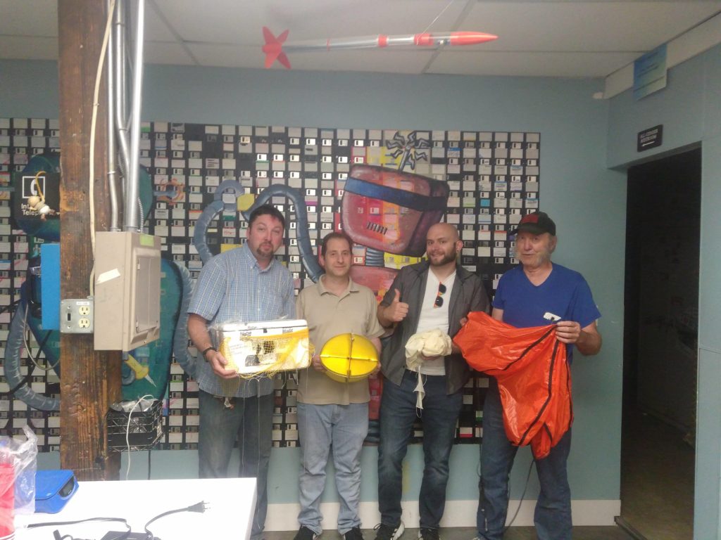
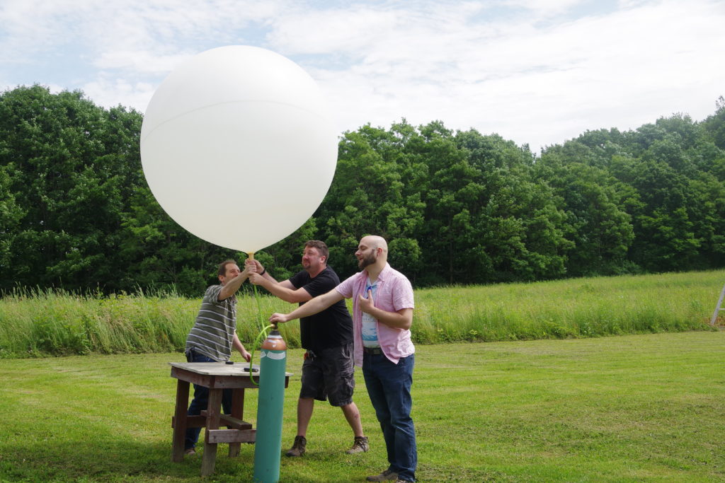
On June 29th., 2019, four members of Triple Cities Makerspace launched, tracked, and recovered a high-altitude balloon.

Left to Right: Gary Dewey (KD2PYB), Adam Biener, Erik Leonard, John Flinn (N2NOL)

The balloon used was a 600-gram weather balloon filled with around 100 cubic feet of helium.

Inflating the balloon with helium.

The payload consisted of: an HD video camera, an APRS radio transmitter to transmit GPS and altitude data, and a Slow Scan TV transmitter.

The balloon’s payload

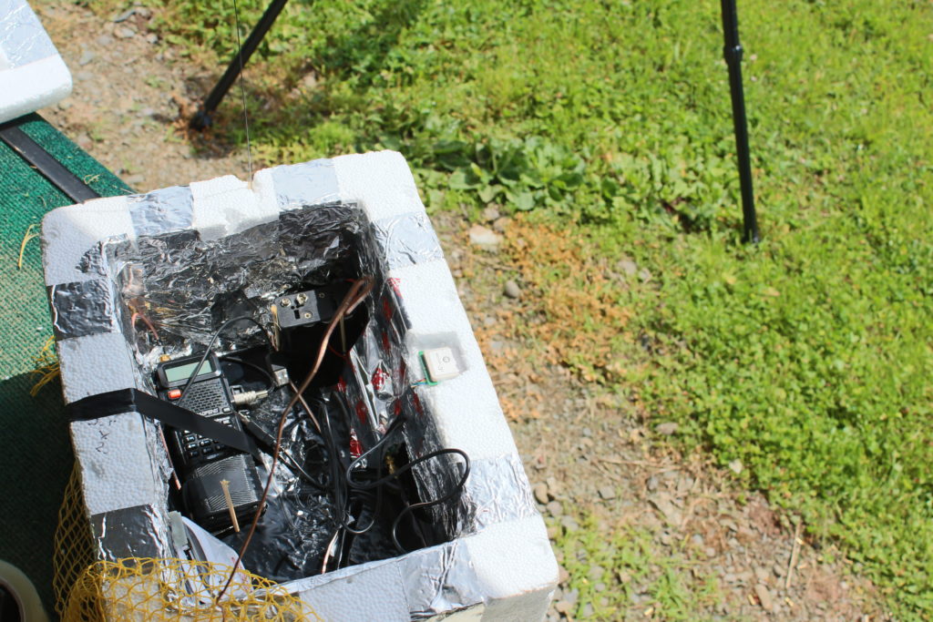
The APRS (Automatic Packet Reporting System) transmitter module was supposed to send live GPS coordinates and altitude information on the frequency of 144.390 MHz to any listening I-gates (radio internet gateways) for the duration of the flight.

The Slow Scan TV system consisted of a Raspberry Pi Zero with a Pi camera and a digital to analog converter sound card. The Pi was set up with a Linux daemon script to repeatedly snap a photo, convert it to a Martin-1 Slow Scan TV audio file, then play that file out through a radio transmitter. This would allow us to send live photos during the flight to amateur radio listeners all over the Northeastern region of the United States!

Both of these systems were tested before being assembled and incorporated into the balloon payload container, but both systems experienced problems during the first half of the flight, as the balloon ascended to its peak altitude with the payload. The APRS transmitter was “stuck on” and sent a non-decodable signal for the duration of the first half of the flight, and the SlowScan TV system’s scripted repetition delay of 1 ms ended up providing insufficient time for the camera to adjust for sun saturation, as the first half of the mission the system sent “green” frames.

Initial SSTV pictures.

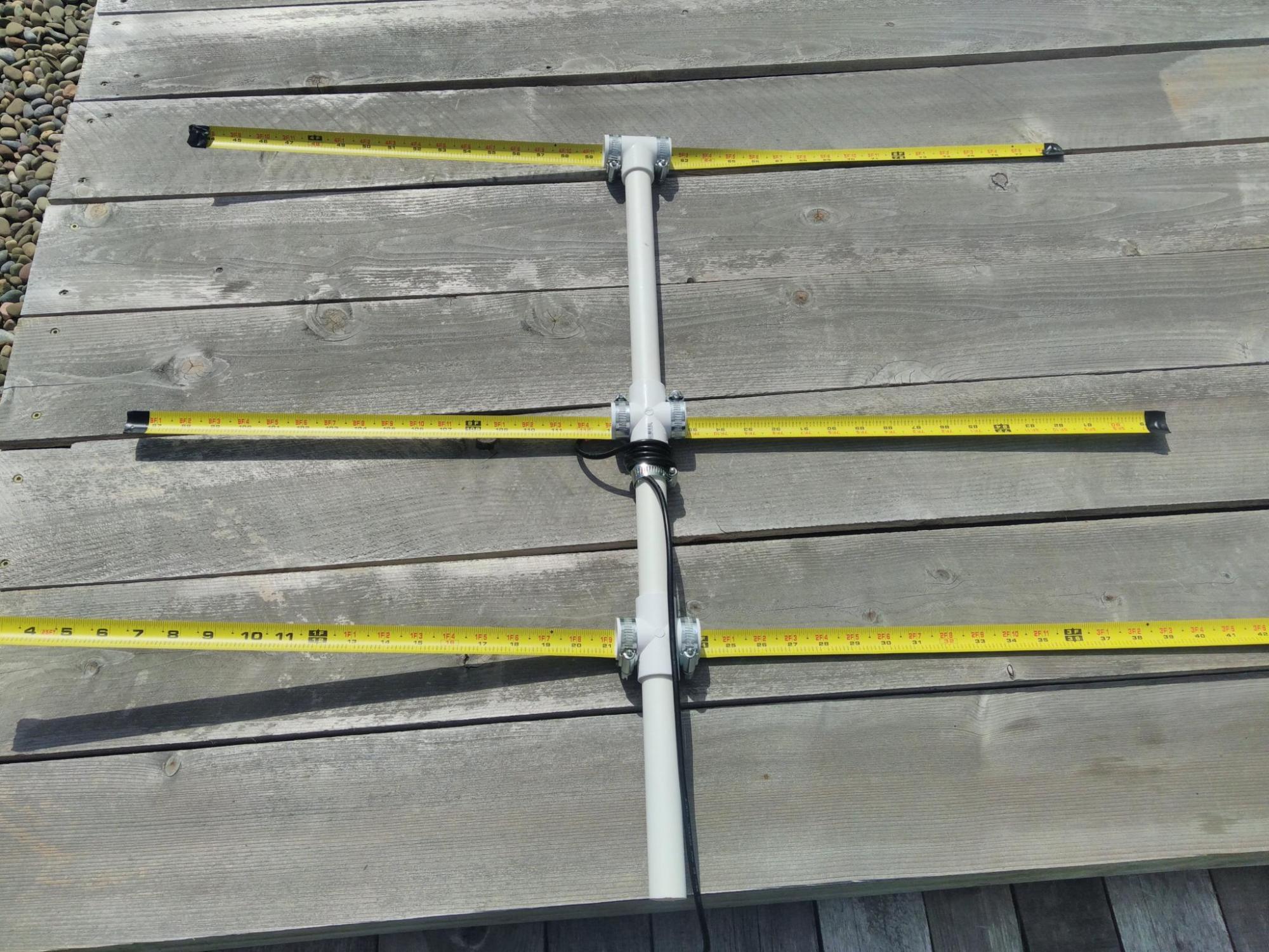
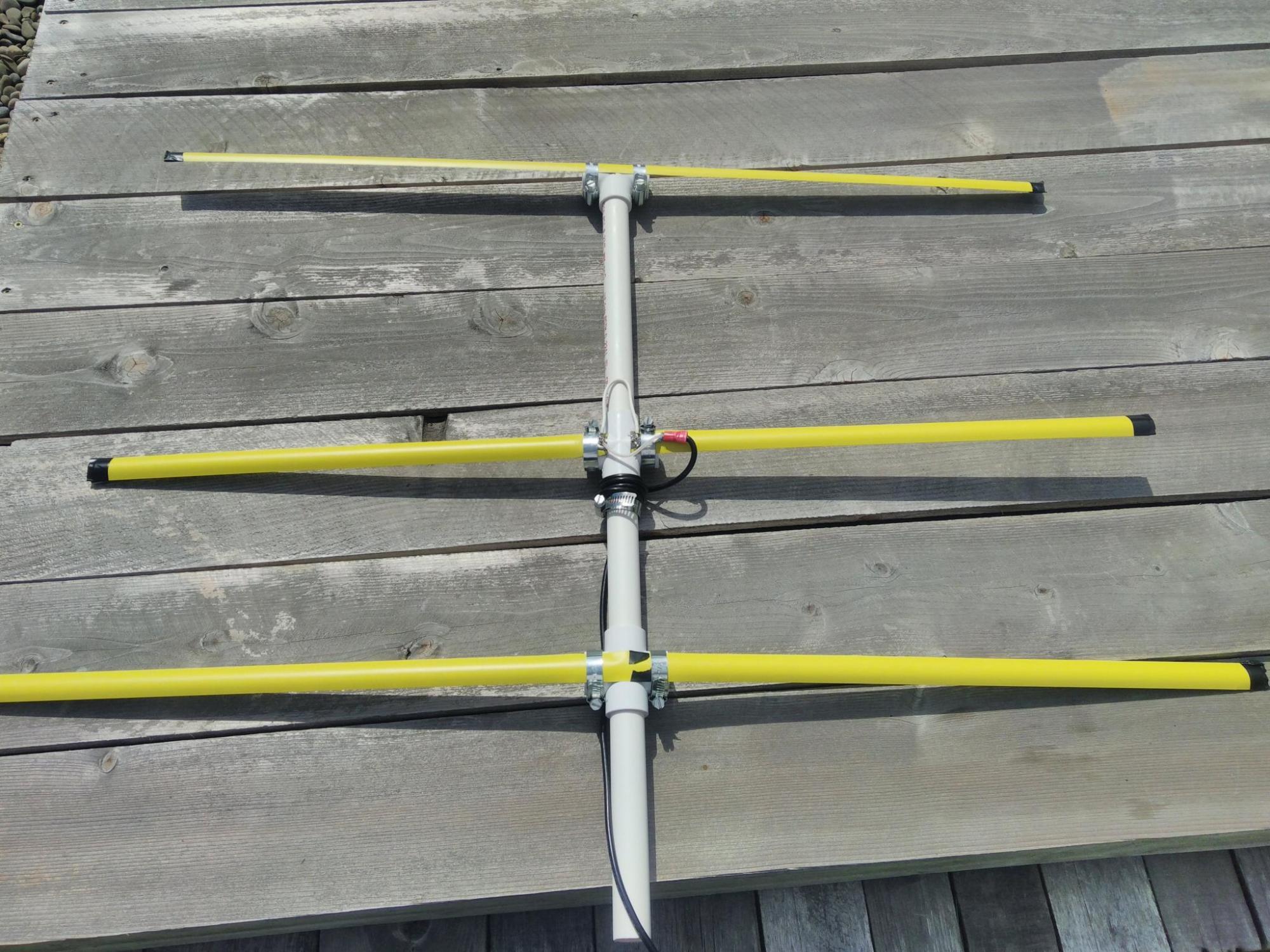
Given these problems, the TCMS recovery team decided to attempt to track the balloon along its predicted flight path by following Route 17 East. We pulled off the highway in Hancock, NY, and attempted to “find” the direction the balloon was traveling by using a directional yagi antenna and the balloon’s SSTV signal.

Predicted flight path, generated using https://predict.habhub.org/

Erik then noticed that the SSTV system had started to produce “non-green” photos! Apparently the balloon had reached an altitude where the sun’s image saturation was less of a problem.

A SSTV photo of the upper atmosphere!

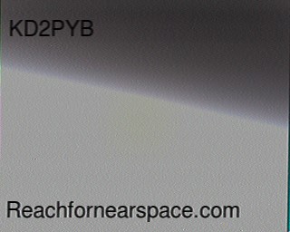
Around this time many amateur radio operators from other states started capturing images and uploading them to the project’s website https://reachfornearspace.com/users-post-gallery/

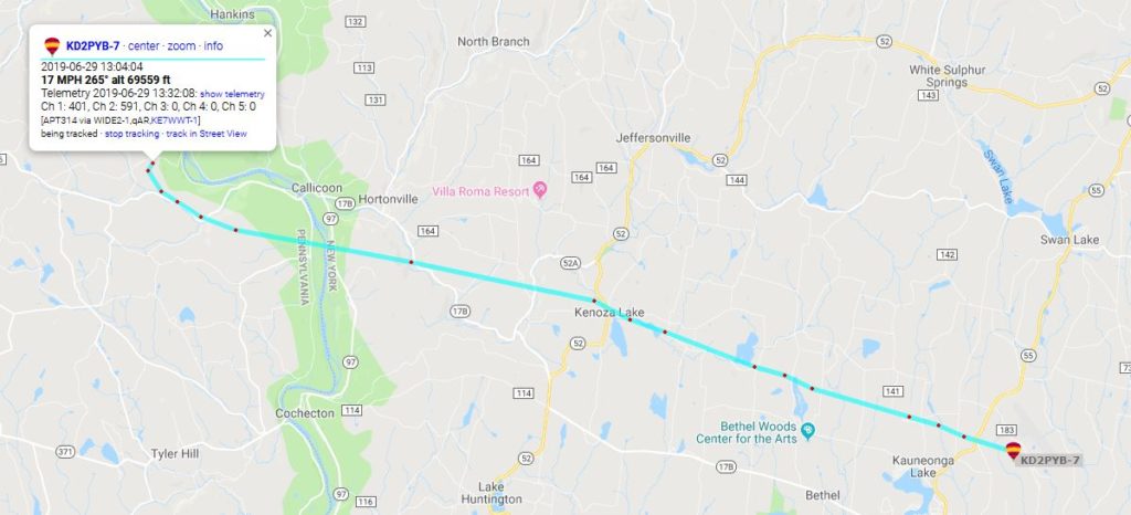
Unfortunately no data was generated when the balloon reached its peak altitude, but we estimate that it ascended to ~70,000 feet as the APRS GPS system started transmitting data while descending, and the first packet transmitted recorded an altitude of 69,559 feet.

APRS data packets received during descent.

The furthest SSTV signal report came in from Cleveland, Ohio, with an estimated signal distance of ~342 miles!

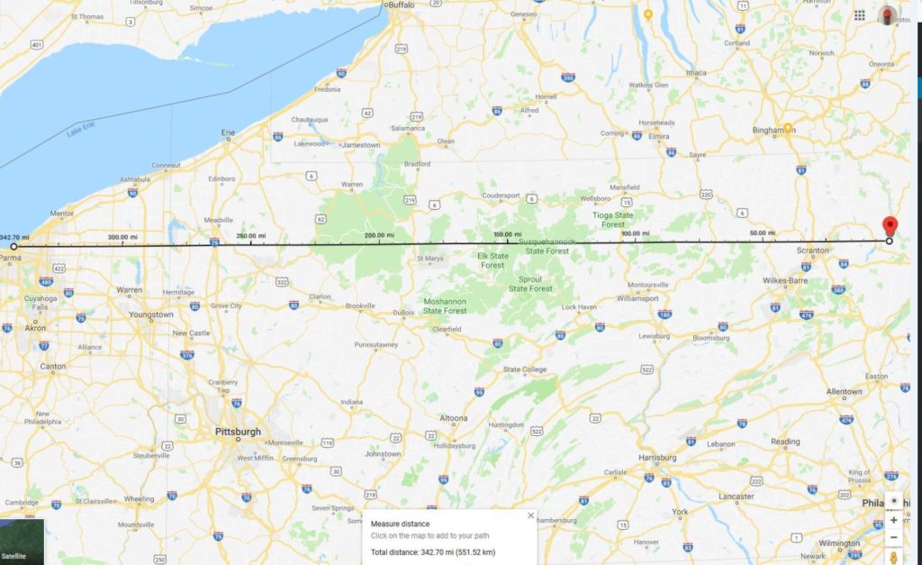
Cleveland is just barely within line-of-sight signal range of the balloon with an altitude of ~70,000 feet:

SSTV coverage shown in the purple radius.

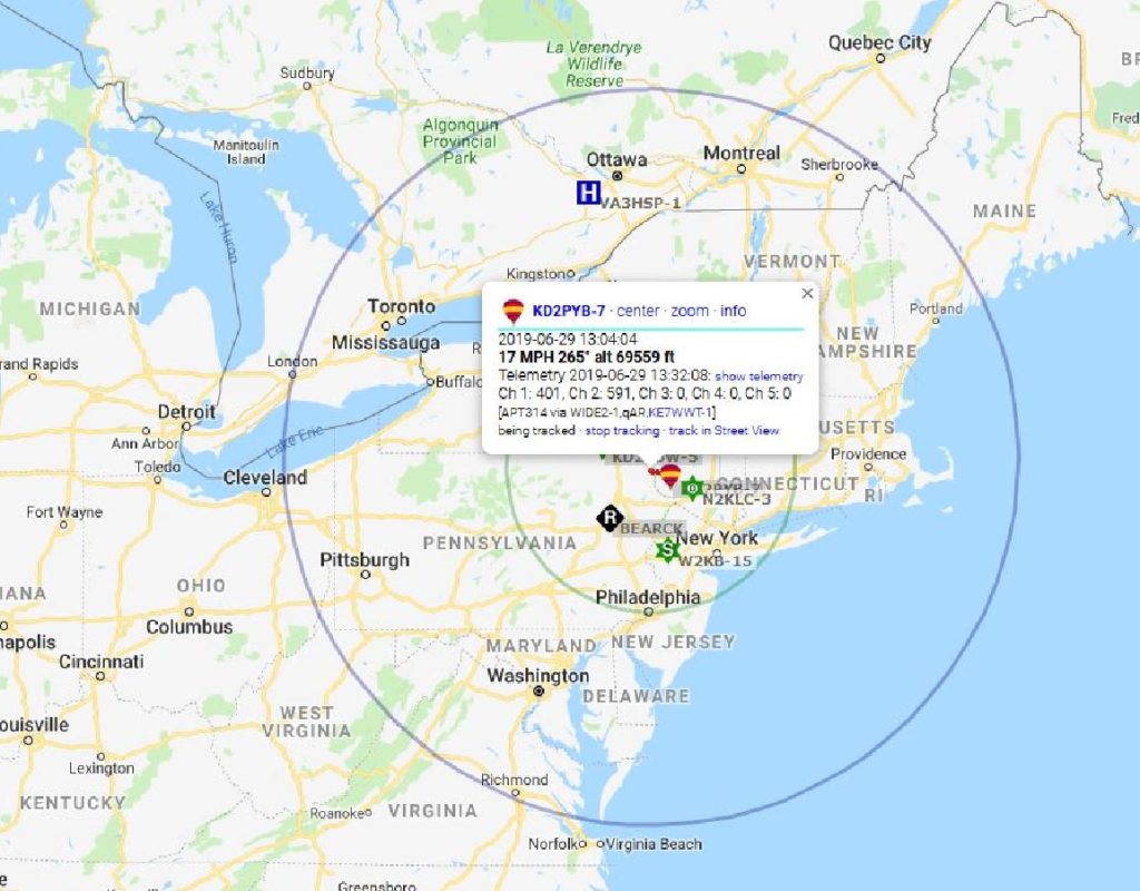
Other signal reports came from Connecticut (~111 miles), Maine (~292 miles), Maryland (~234 miles), and Rhode Island (~196 miles)!

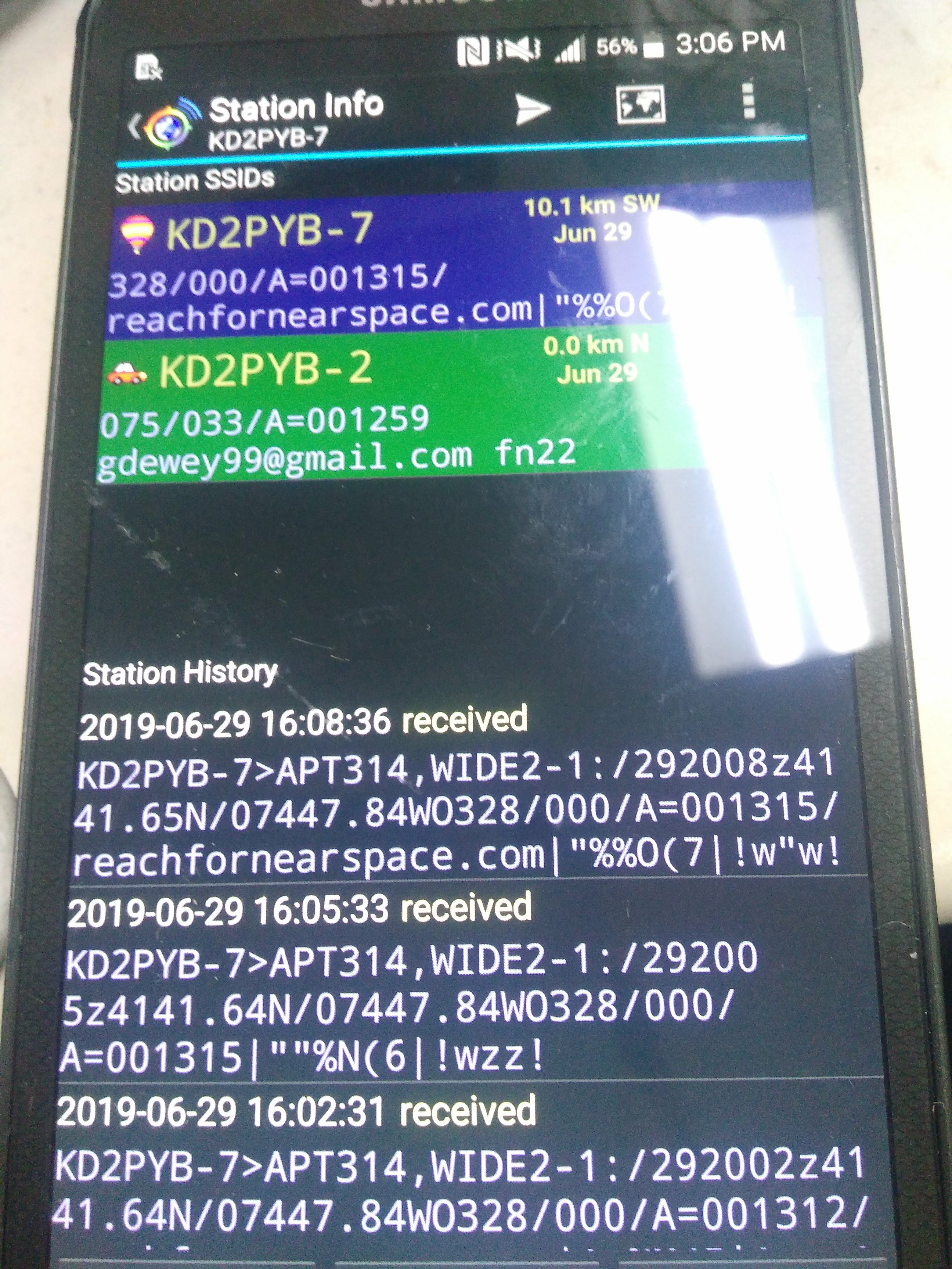
The last APRS packet was transmitted near the Sullivan County Airport at an altitude of ~3000 feet.

Last APRS packet received by an I-gate.

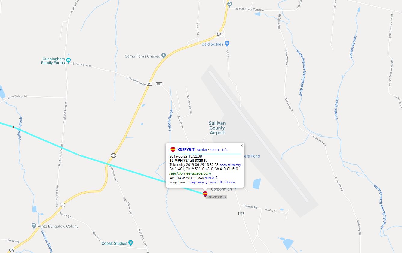
We drove to the airport and attempted to find the balloon and its payload with the help of the airport’s personnel. Because there were no local i-gates (APRS Internet Gateways) nearby, we didn’t initially have the payload’s final GPS coordinates; but using a handheld radio and the apsdroid app on my phone, I was able to receive a signal and retrieve the final GPS coordinates!

Final GPS coordinates!

We retrieved the payload shortly afterwards; its parachute allowed all of the equipment to land without damage, and we retrieved HD video footage of the balloon’s ascent from the HD camera’s microSD card! The camera recorded in 5 minute segments, which we stitched together and uploaded to YouTube:

Full ascent in HD

Here is the final video segment recorded near the peak (apogee) of the balloon’s flight; the camera shut off shortly afterwards for reasons unknown:

Apogee footage.

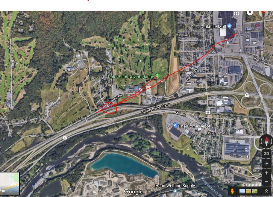
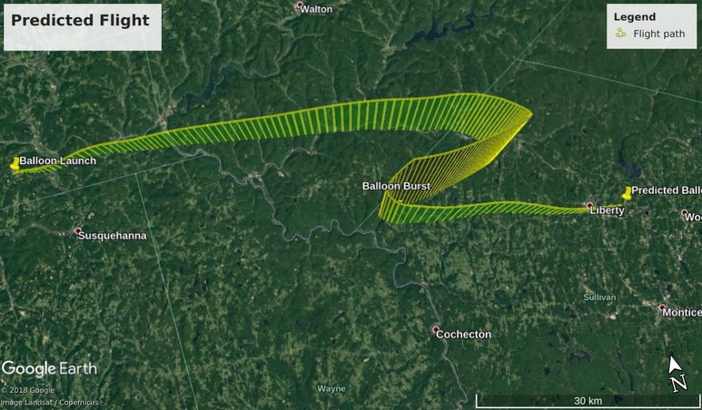
We have no APRS data for the balloon’s ascent, but we can compare the predicted vs the actual data for the balloon’s descent:

Predicted VS Actual APRS data.

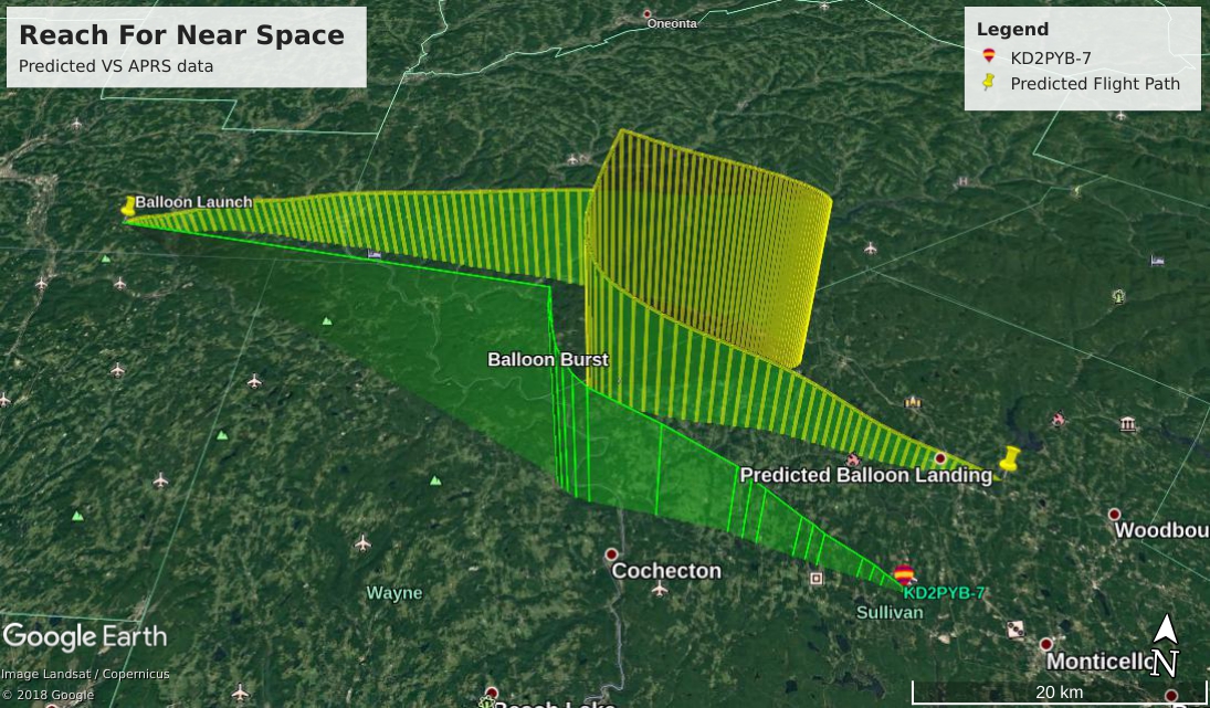
There is also no video footage for the descent, but it can be simulated by putting the APRS data into Google Earth:

Simulated Landing footage.

Despite the problems with the APRS transmitter and SSTV camera saturation, this was a fantastic project and experience! I have learned a lot about radio, public relations, web programming and more in the process, and intend to try a similar project soon.

Special thanks to the Triple Cities Makerspace Crew for assisting me with the balloon launch and recovery, and thanks to all participating radio operators: W3AVP KB1PVH W3BAS N3CAL AC1GX N9AGC K6LPM KY1K KB3PQT N2TMS KB2BLS NP2GG N3EPY N3FWE KC9ONY WB8REI N8WAC

All photos and video footage courtesy of and property of Gary Dewey.

Fox Hunt: A Radio Adventure

A few months ago I had the opportunity to participate in something called a “fox hunt” – or a hidden transmitter hunt – with the Binghamton Amateur Radio Association (BARA). This activity brings together a group of people to find a radio transmitter which has been hidden and is broadcasting on a specific frequency; they are tasked with finding the transmitter based on radio signal strength, which is usually accomplished by using a directional antenna, such as a yagi antenna. The term ‘directional’ in the context of radio antennas means that the antenna picks up a signal best when it is aimed at the source.

Prior to the hunt taking place, BARA offered a class where we made directional yagi antennas out of cheap, simple materials like PVC pipe and tape measures (see pictures below). I used the antenna I created with a radio having an ‘s’ meter, or signal strength meter, so that I could visually observe and measure signal strength of the hidden ‘fox’ (or transmitter). The general strategy of ‘foxhunting’ is to find at least 2 places where you can point the antenna and “shoot a bearing” (get a compass direction) on the signal; where these two imaginary lines intersect on a map should be close to where the hidden transmitter is located. This strategy is similar to how cell phone signal triangulation and the GPS works!

I started searching for the ‘fox’ at my house, moving my antenna in all directions while listening in on the pre-specified frequency. I didn’t hear anything, so I decided to drive to the Oakdale Mall to see if I could hear anything from there. When I tried again from the mall, I could hear a signal with medium strength (S5) on that frequency when my antenna was aimed towards Endicott, so the next step was to drive towards Endicott to get another ‘fix’ on the signal’s transmitting location.

Driving towards Endicott on Watson Blvd., I stopped to shoot a bearing at the Polar Driving Range. I was getting an extremely strong (S9) signal reading from there, so I figured that the transmitter must be close by. As it turned out, the hidden transmitter WAS nearby: it was hidden at the Elk’s Club on Watson Blvd.

Fox hunts are a great way to develop skills in orienteering, and can be useful for search and rescue operations as well! These skills will also come in handy on my upcoming high altitude balloon project, in which I’ll track the balloon using APRS and hopefully recover it using readings of the balloon transmitter’s signal strength at its landing site. I’m looking forward to my next fox hunt!

Picture credits:

All photos provided and owned by Gary Dewey.

Drinkbot DIY project!

Hello!

One of the coolest projects yet to emerge from the Triple Cities Makerspace is the Drinkbot, a Raspberry Pi-controlled fluids pump and mixing system which allows you to create a beverage from up to six different sources of fluid, as set up by its web server-hosted frontend. You can read all about it in the website linked below, including schematics and parts information:

Drinkbot

Keep on making! 😀


The Basics of Cryptography, part 1

Encryption has been a buzzword in the technical world for the past few decades; but in light of recent events, such as the San Bernardino terrorism case, encryption has become important to the average person as well. Encryption is a procedure for taking ordinary information (known as plaintext) and converting it into an unrecognizable format (known as ciphertext). The history of encryption can be traced back as far as Julius Caesar, who used a substitution cipher (as shown in picture 1, below). A cipher is a pair of algorithms used to encrypt and decrypt data, like an equation. In a substitution cipher, you substitute characters in your message with other characters using some sort of scheme. In this way, Caesar would send encrypted messages to his army. For example, let’s say the substitution key is 3, so each letter is shifted to the right by 3. Using this key, “hello reader” becomes “fcjjm pcybcp”.

As you may be able to tell, this cipher is vulnerable to an attack known as frequency analysis or pattern words. In this attack, the most frequent letters are tallied and matched up with the most frequently used letters in the alphabet; with enough pattern-matching, the substitution key can usually be derived.

Another classical cipher used was the transposition cipher, where the letters are rearranged somehow to jumble the plaintext. A modern example of this which you may know is “pig latin”, where you take the first syllable of a word and move it to the back to form a new word.

The Greek military is also thought to have used stenography, which is hiding a message in plain sight. They did this using something called a scytale: they would wrap a parchment around a wooden rod, write their message on the parchment, then unwrap the parchment and add letters in between those already written (see picture 2, below). Only someone with an identical wooden rod would be able to decipher the message. Another example of early stenography was tattooing a message on a slave’s shaved head and waiting for the hair to grow back to cover up the message.

Skytala
Skytala

Stenographic methods have become increasingly complex over the past couple of millennia, with forms like invisible ink, microdots, and hiding information in the compressed space of music files (as seen in the tv show Mr. Robot) becoming popular. Another common method is to store your secret information in a photo file, since these files are also compressed and do not require all the bits to recreate the photo.

These methods of concealing information for secure communications are apart of a larger family of study called cryptography, which in Greek translates to hidden or secret writing. A fairly famous example of cryptography is the Enigma device, used by the German military during WWII to send secret messages. The large computer systems developed to help crack the Enigma code helped usher in the modern age of computers. Fast forward to today, and cryptography is used every day by ordinary people, not just spies and military personnel. Online banking and credit card transactions, email, electronic voting, anonymous web surfing, regular web surfing and social media are all areas where modern cryptography is used without many people ever realizing it.

In the information security world, there is a principle known as the C.I.A. triad, which stands for Confidentiality, Integrity, and Availability. Confidentiality is the ability to keep your information safe and secure from unauthorized entities, which can be equated with privacy. Integrity deals with the consistency, accuracy, and confidentiality of your data. Availability is just what it sounds like: having your data or services available to you and whoever else needs access at all times.  Cryptography can aid in confidentiality and integrity. As we have discussed earlier, encryption supports confidentiality by ensuring your message/data is not readable by an unauthorized party. Integrity is supported by using various cryptographic algorithms to ensure data has not been tampered with or altered; i.e., the original data is put through an equation to derive an ‘answer’, which you receive a copy of. If you then receive a copy of the data, put it through the same equation, and receive a different ‘answer’, your integrity check fails. These checks are sometimes known as hashes, of which there are various types depending on the algorithm used. They are used in a wide variety of applications, e.g. proving the integrity (lack of tampering or file corruption) of files downloaded from the Internet by checking them against their authenticated hashes or checksums.

Modern cryptography for confidentiality can be divided into two categories: symmetric key cryptography and public key cryptography. Symmetric key cryptography uses the same password or passcode to encrypt and to decrypt the data. This can be a security concern because of low confidence regarding secure sharing of the password. It may be a decent algorithm / scheme to use to encrypt data for your own use, which is what most full-disk or file system encryption systems use, but it’s not recommended for use when sharing data among multiple users. This scheme may be used to encrypt multiple kinds of devices: laptop hard drives, phones, tablets, flash/thumb drives, individual files, and so on.

The preferred method used to encrypt data shared among multiple users is public key encryption, which uses two different keys: a public key and a private key. The public key is just that, public; it’s the key you give to any other user, and can be publicly known. The private key is also just that, private, and is related to the public key in a way such that it can decrypt something encrypted with the public key. Anyone can encrypt a message for you using your public key, which you can then decrypt with your private key, which nobody should know except for you. Public keys can be also digitally signed by other users with their private keys, which means the people that have signed the key have verified the key owner’s identity. This creates a web of trust. Let’s say Don trusts/knows Bob but not Alice; since Bob trusts/knows Alice, Don inherently trusts Alice’s key/identity due to his trust of Bob.

A good example of a public key encryption system is GPG (GNU Privacy Guard), a free replacement for PGP (Pretty Good Privacy), as PGP used to be free but was bought by Symantec. GPG public key encryption can be used to encrypt email messages and files, and also has some built in features for integrity (verification of user identity). For example, let’s say Alice wants to email Bob a secure message. Alice could look up Bob’s public key from a public key server, or get it directly from Bob and use it to encrypt her email to Bob. She then digitally signs her message using her private key. When Bob receives the email, he decrypts the message using his private key, and verifies her digital signature using Alice’s public key.

Thank you for joining me for a brief history and overview of cryptography and encryption! Stay tuned for future blog posts where I hope you will join me as we explore cryptography and encryption in more detail. You will learn how to better protect yourself and your data in today’s computer age.


Text References and Resources:

“Cryptography: History of cryptography and cryptanalysis.” Wikipedia.org. Wikipedia, 25 July 2016. Web. 1 Sept. 2016.

“GNU Privacy Guard.” Wikipedia.org. Wikipedia, 15 Aug. 2016. Web. 1 Sept. 2016.

“Outline of cryptography.” Wikipedia.org. Wikipedia, 21 July 2016. Web. 1 Sept. 2016.


Picture References:

Skytala. Digital Image. Wikimedia Commons. Wikimedia Commons. 16 Feb. 2007. Web. 1 Sept. 2016.


Resources:

The Electronic Frontier Foundation, https://www.eff.org.

A History of Aircraft Simulators in the Triple Cities

Link’s “Blue Box” – the first aircraft training simulator

Many people who live in Binghamton are aware of the long history of technological research, development, and manufacturing work done locally by companies like IBM, General Electric, BAE, and Lockheed Martin, with many cool products in the computing and military realms being developed here. It is often forgotten, however, that some of the first aircraft simulators ever created were developed here by a local entrepreneur named Edwin Link!

The son of a pipe organ manufacturer, Link developed an interest in flying in the 1910’s, and began taking flying lessons around 1920 or so. Frustrated by the lack of any devices that could provide training for potential fliers before stepping into a cockpit, Link worked with engineers and mechanical assemblers from the Link organ factory in the late 1920’s to design and build a mockup of a then-contemporary airplane cockpit with controls operated by air pressure from a bellows adapted from those used in the Link pipe organs! This cockpit was mounted on a platform which could move in three dimensions – tilting forward or back with the pitch control, rolling left or right with the roll control, or yawing horizontally left or right with the pedals. This motion of the platform, tied with input from the pilot into the corresponding controls, provided a simulation of the motion of an aircraft in flight, in three dimensions; this concept is still key to realistic (FAA-certified) flight simulators in use today by commercial or military pilot training schools.

Link initially manufactured a few for use at amusement parks or for training at local airports (including Endicott and Cortland), but saw the potential for widespread commercial application as the market for airplanes outside of the military and stunt/barnstorming markets increased; and he began promoting his simulators around the country. His commercial breakthrough came when the U.S. Army Air Corps (which would become the Air Force after WWII) began transporting air mail for the U.S. Post Office in 1934, and experienced many fatal accidents when new pilots encountered inclement weather or other unfamiliar flying conditions. Link demonstrated his simulator to officials from the Air Corps, and they were sufficiently impressed by it – as well as by Link’s ability to fly in hazardous weather using instruments and training acquired through use of his simulator – to place an order for 6 trainers. When the pilots who trained using these simulators demonstrated remarkably improved abilities compared with their peers, the Air Corps ordered more, and Link’s fledgling Link Aviation Devices company began producing the little “Blue Box” simulators (as they were nicknamed) from their factory in Hillcrest, just north of the city of Binghamton. The onset of WWII and the success of the Air Corps’ training using these simulators convinced the U.S. and U.K. militaries to order thousands of them, and Link’s simulators were soon seen as essential for use in training military pilots. As the commercial aviation industry expanded after the second World War, initially using some of the same aircraft used by the Allied forces and flown by ex-military pilots, Link expanded into this field as well, and became the preeminent aircraft simulator manufacturer for the next three decades, providing training equipment for governments and corporations around the world and even supporting special projects like Lockheed’s SR-71 Blackbird and NASA’s Apollo program.

After corporate mismanagement, international competition, and a hostile takeover resulted in the dismantling of Singer-Link (the successor to Link Aviation Devices) in the late 1980’s and early 1990’s, several companies picked up the pieces and continued the legacy of aircraft simulator design and manufacturing, including L-3 Communications, which still has a presence in the Binghamton area today and is responsible for the creation and maintenance of aircraft simulators for programs like the United States Air Force’s C-17 cargo planes. Several other companies in Binghamton also thrive on the legacy of Link’s simulators, including KRATOS Technology and Training Solutions and Simulation and Control Technologies – both of whom design and manufacture aircraft simulators in the Binghamton area – and BAE and Lockheed Martin, who use aircraft simulators created by companies like these to develop avionics hardware and software for commercial and military applications in Endicott and Owego. Decades after Edwin Link was inspired to find a better way to teach himself how to fly, the technological field he pioneered is still a vital part of the training processes for thousands of pilots around the world, and is still a major component of the Triple Cities’ economy.

Sources:

“Link, Edwin Albert”. Nationalaviation.org. The National Aviation Hall of Fame, 31 Oct. 2016. Web. 3 Nov. 2016.

“L-3 Link Simulation & Training: History.” Link.com. L-3 Link Simulation & Training, 31 Dec. 2012. Web. 3 Nov. 2016.

Tomayko, James E. “Crew-training simulators.” NASA.gov NASA April 1987. Web. 3 Nov. 2016.

Triple Cities Makerspace at the World Maker Faire!

Maker Faires are “all-ages gathering[s] of tech enthusiasts, crafters, educators, tinkerers, hobbyists, engineers, science clubs, authors, artists, students, and commercial exhibitors”, organized by Maker Media (who also publish Make: magazine) to promote the creativity of these individuals and organizations at specific venues around the world. One of the largest of these gatherings is held in New York City every year in the fall, typically at Flushing Meadows Corona Park in the Hall of Science. Triple Cities Makerspace has had an active presence at the NYC World Maker Faire for the past three years, hosting a booth in the Makerspaces compound at the Faire to promote the activities and projects of individual TCMS members and the organization as  whole. The Events Committee is responsible for this booth and the projects featured inside it which, this year, consisted of Cliff’s 3D printer, Eric’s “Doctor Who” chess set, Adam’s “Drink Bot” (upgraded with an aluminum frame and a Raspberry Pi 3 controlling all of the hardware), and Leslie’s geometric piece building set). The booth was manned by various members of the Committee throughout the entire weekend of the Faire, rotating through several shifts to allow everyone to appreciate all of the other exhibits at the Faire. Several other members of the Makerspace came down for the weekend to check out all of the awesome stuff at the Faire as well, and their photos of the booth and other exhibits at the Faire are featured in the Google Photos album linked at the bottom of this blog post, along with photos taken by the members of the Committee. We look forward to attending 2017’s Faire!

Faire photos are available here, c/o Kris Brown.

Sources:

“Maker Faire: A Bit of History.” Makerfaire.com. Maker Media, 1 Jan. 2017. Web. 3 Jan. 2017.