Blog

Project Profile: Magic Wheelchair Costume

Members of the Triple Cities Makerspace recently completed the largest group project undertaken at the Space in quite some time, in collaboration with the Magic Wheelchair organization and an independent artist in Cortland, NY named Crystal Lyon. This project was the creation of a Halloween costume for a child afflicted with cerebral palsy, who lives with his family in Cortland. The child, Jacob Eldred, has never been able to take part in any Halloween festivities due to his condition, although he has always wanted to. His family contacted Magic Wheelchair, an organization which works with local artist, makerspaces, and families of children like Jacob around the United States to create costumes for disabled children according to the children’s preferences and interests, to see what could be done for Jacob. In turn, a Magic Wheelchair representative named David Vogel spoke with Crystal Lyon (as a prominent Cortland artist interested in such activities) and Erik Leonard (as the president of the nearest makerspace to Cortland) regarding the creation of a costume for Jacob; as Erik was then preoccupied with other TCMS affairs, he turned over the matter to long-time TCMS friend Amanda Truin, who acted as project lead and as a liaison between Jacob’s family, Crystal L., David V., and a variety of TCMS members who agreed to work with Amanda to create a costume for Jacob.

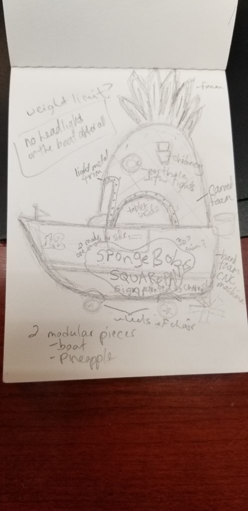
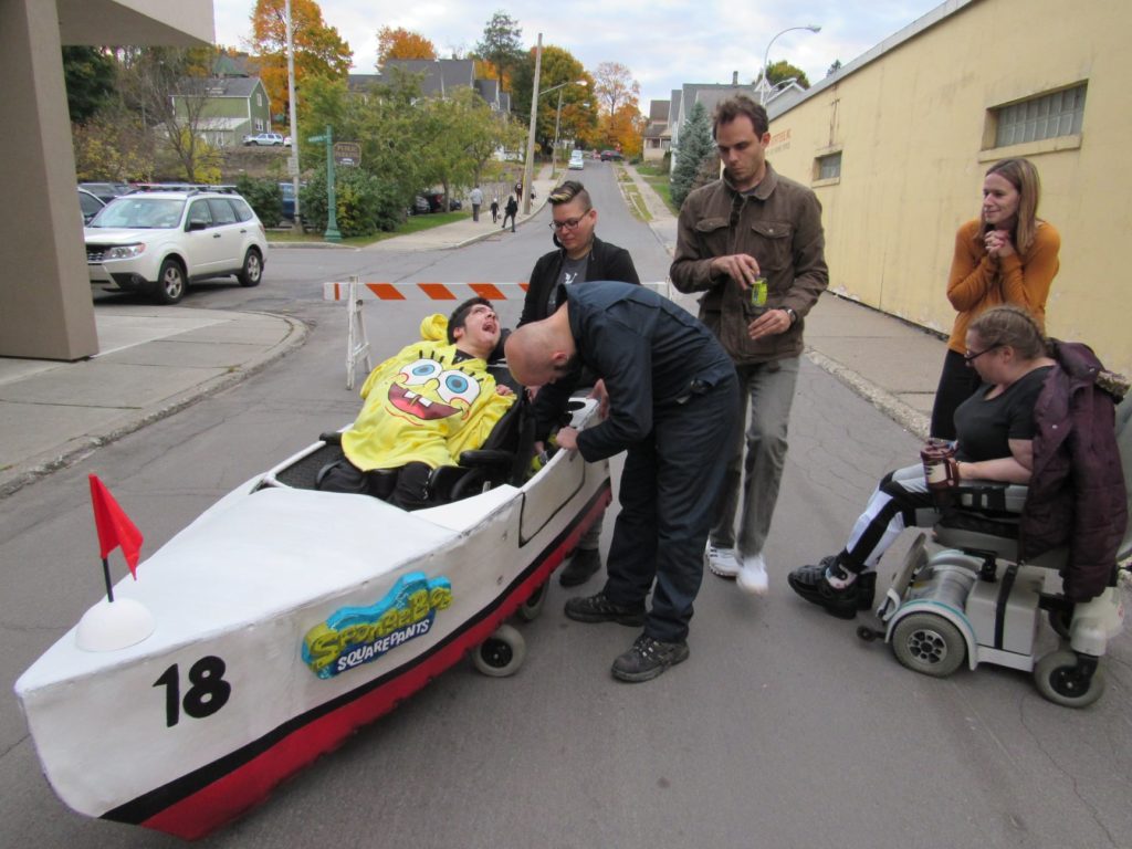
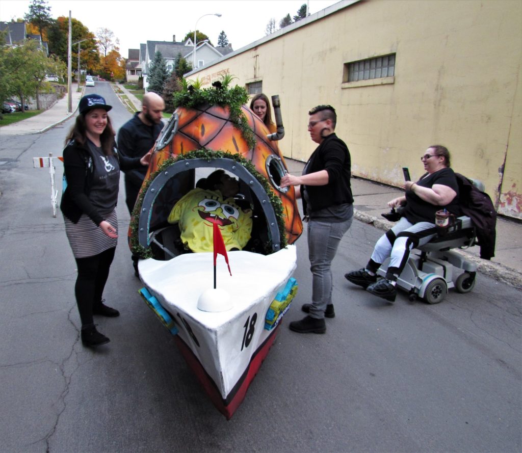
Following perusal of the costume-creation process documentation and personal profile of Jacob passed on by Magic Wheelchair, Amanda, Crystal, and Cliff Burger (TCMS vice-president) conducted a more in-depth interview with Jacob and his family regarding Jacob’s interests and likes/dislikes. As one of Jacob’s favorite TV shows is “SpongeBob SquarePants,” Amanda was inspired with the idea of creating a costume combining two iconic objects from the show (SpongeBob’s pineapple home and boatmobile), as it would be a visually striking costume that had not been done by any other Magic Wheelchair team project. This costume idea would incorporate sound clips from the show, LED lights, and feature colorful paintings and decorations evocative of the TV show. After Jacob and his family indicated their approval of this design idea, Cliff obtained measurements of Jacob’s wheelchair, including points where the costume could be attached to the wheelchair, and set about creating a CAD model of a basic structure for the costume.

Amanda’s design concept sketch

Following this meeting and the creation of design models and sketches by Cliff and Amanda, they sat down with other TCMS members – including Erik and Ethan Bexley – to decide upon a timeline for construction of the costume and assign design or construction tasks to specific people. Ethan took the time to create a project in Asana (a work-management software
platform) to coordinate task assignments and management among the team members, as well as to facilitate the sharing of files pertinent to this project; this made organizing the initial stages of the project much easier than otherwise, especially when the initial timeline was shortened with the goal of completing the costume by the time of the annual Cortland Halloween parade.

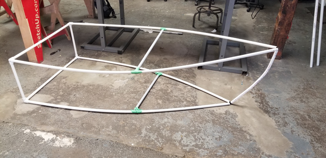
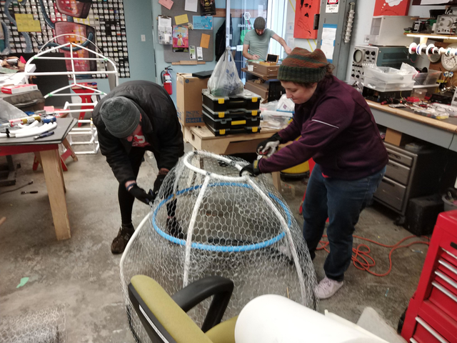
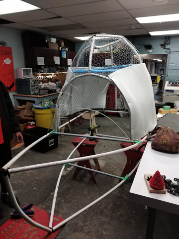
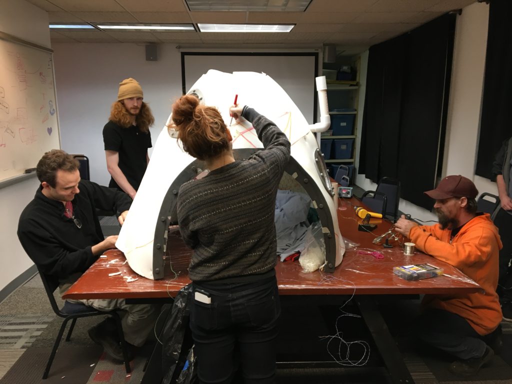
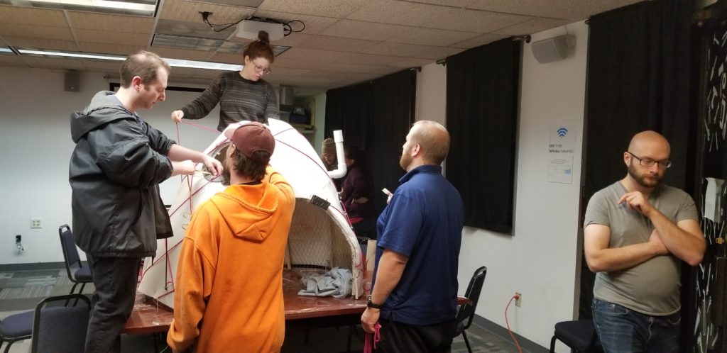
The heart of the costume is its structure; this was a somewhat improvised affair based on Cliff’s design models, constructed with the goal of being strong yet lightweight and made from inexpensive and easily-obtainable materials. The structure of both the pineapple and boat portions of the costume is largely made of PVC pipe, lightweight foam sheets cut to size, and chicken wire, all held together with various adhesives, zip-ties, and screws. The pineapple even has an unexpected element in the use of a hula hoop to help form its rounded shape! Two major challenges encountered during the structural construction process were the organic shapes of the pineapple and boat, being non-conducive to construction with building materials intended for rectangular objects, and incorporating the mounting points assemblies of and access to the wheelchair into the structure in such a way that the costume could be attached / detached to and from the wheelchair with relative ease. These challenges were overcome using innovative construction techniques including bending PVC pipes into permanent curved shapes using a heat gun and sand dispersed inside the pipes to prevent excessive heat buildup in any one place, which would result in structural weaknesses, and making use of chicken wire as a structural element for the pineapple (as a pineapple is a very unconventionally-shaped structure). The makers even 3D printed fittings for the PVC pipes when conventional sizes would not work for what was needed. Many long hours were spent acquiring materials, assembling, and reworking the structure during this phase of the costume’s construction.

Preliminary boat structure (before additional bracing was added)
Pineapple structure being assembled
Both structures temporarily connected for fitment purposes
Pineapple structure being covered with foam

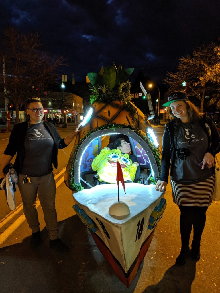
While the structure was being assembled, Adam Biener worked autonomously to devise the electronic circuitry and software used to provide LED lighting and sound effects for the costume. He created, tested, debugged, and reworked the circuits, controls, and software until it was fully functional, tailoring the sound effects used to Jacob’s specific preferences and creating a special control handle which Jacob could manipulate to activate the lights and sound effects. The electronics assemblies were mounted in the rear of the boat’s structure, and the LED lights were attached to the pineapple structure, with final wiring being done once the two structures were connected to one another. Enormous credit is due to Adam here for successfully undertaking almost the entirety of this portion of the project on his own, with some additional help from John Sheak.

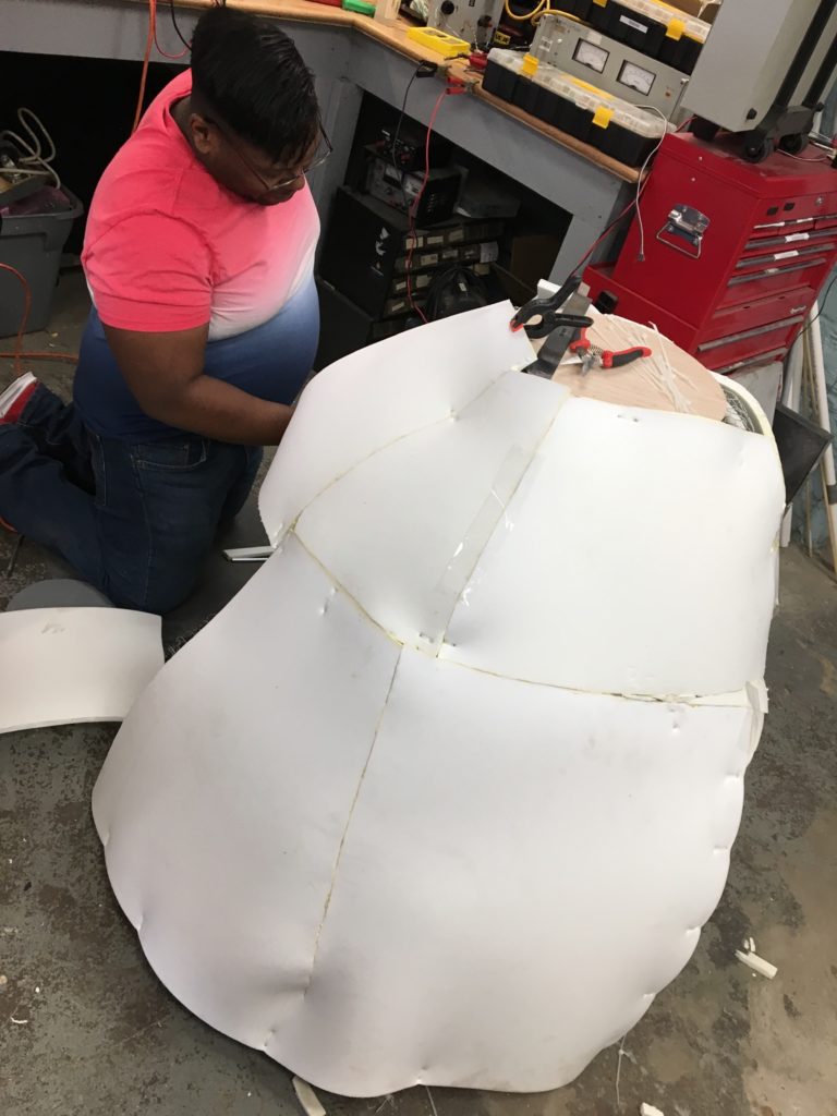
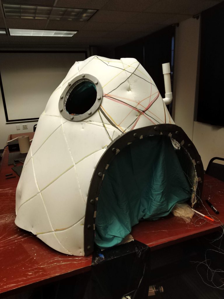
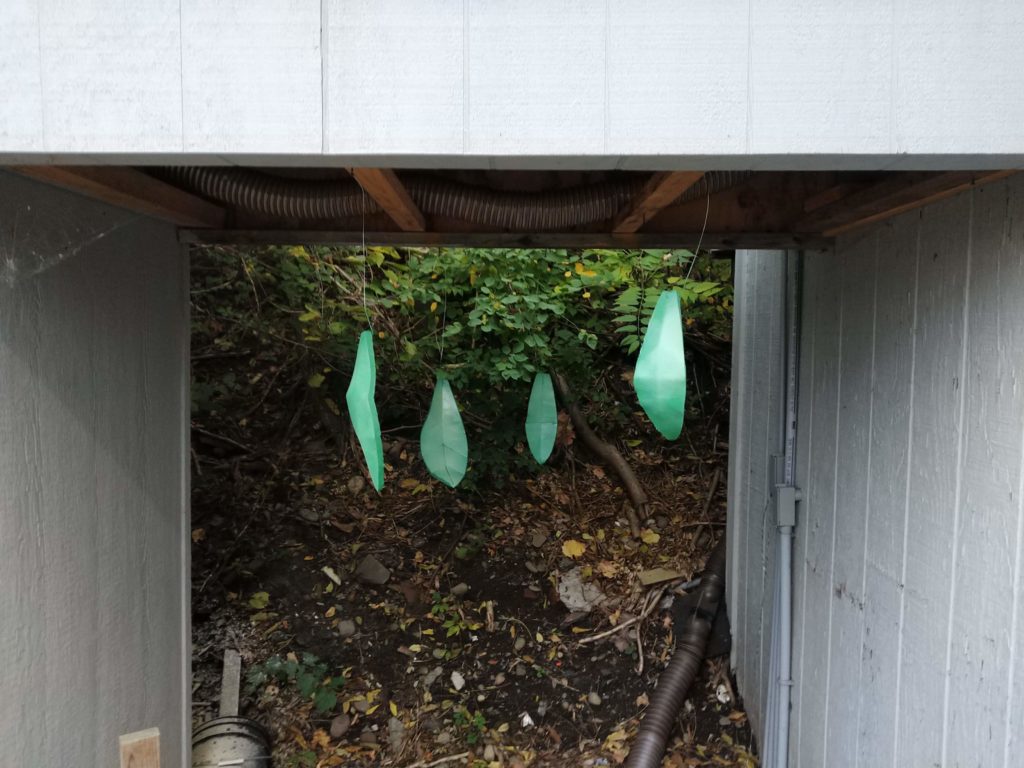
Once the structures were largely complete, Amanda began decorating the pineapple and boat with help from several other TCMS members (credited at the bottom of this blog post). The pineapple and boat structures, each covered with foam, were sanded and painted with several layers of primer and paint, with the pineapple’s foam having been scored with knives to have the texture of an actual pineapple. Special painted highlights in lighter colors were added to various portions of the pineapple, and the scored foam was shaded to give it the appearance of depth and realistic coloring. Foam leaves were cut, shaped, and painted before being attached to the top of the pineapple, and plastic decorative vegetation resembling seaweed was
strewn around the leaves and top of the pineapple to give it the appearance of having been underwater for some time. Amanda painted the interior of the pineapple extensively with various floral and other TV show-appropriate decorations so that Jacob would have cool things to look at when inside the costume, and feel like he was inside SpongeBob’s “real” pineapple! Amanda and Crystal added a final painting element to the boat following the first fitting with Jacob’s family, as Crystal had been assigned the autonomous task of carving the logo for the show out of foam and painting it for the purpose of having an additional visual element on the sides of the boat as well as having some color to liven up the boat.

The pineapple structure, being scored and decorated
The leaves being spray painted
Decorating the pineapple structure
More decorating of the pineapple structure, and fitting the LED strips to the structure’s openings

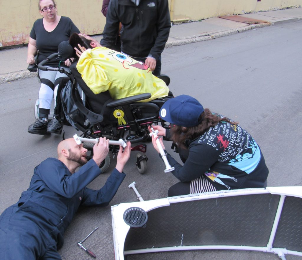
Completion of the costume by the revised timeline was achieved after many long evenings and weekends by everyone involved. Amanda coordinated test-fitting of the costume to the wheelchair with the family and with help from Erik and Cliff; the costume was introduced to Jacob on the day of the parade, and it was attached to the wheelchair with Jacob inside the costume
before he and the family took part in the parade, accompanied by Amanda and Crystal. The costume won first place in the family costume category for the parade, which meant an enormous amount to the family as it was Jacob’s first time participating! The costume remained with the family afterwards; the pineapple was mounted over Jacob’s bed, and his favorite bean bag was put inside the boat as a place for him to watch episodes of “SpongeBob” in! Jacob and his family felt very cared for and happy as a result of all of this, which was the main overall goal of this project and of the Magic Wheelchair organization as a whole.

Assembling the costume supports on Jacob’s wheelchair
Securing the boat portion of the costume to the wheelchair
….and the costume has been assembled on the wheelchair!
Crystal and Amanda with Jacob in the finished costume, in the parade!

All in all, this was a very special project that ended up coming off very well for everyone involved despite the logistical, construction, and timeline challenges encountered along the way, and the lack of familiarity by various project participants with the kinds of design and construction tasks required of them. Special thanks to Amanda Truin for her mature and cool-headed project coordination and for the many long hours spent with every phase of the project, especially the painting and decorating portion; Cliff Burger for making accurate structural models and contributing to the costume’s structural construction, Ethan Bexley for organizing the project
efforts via Asana and for his invaluable contributions to the structure’s construction; and Erik Leonard for helping with every phase of the costume’s construction and handling logistics of costume transportation and setup. As well as these project members, the following members also helped out with ideas, construction, painting, logistics, and/or other work to make this project a success (sorted in descending alphabetic order of last name):

Eric Adler
Adam Biener
Zach Brown
Gary Alan Dewey
Bill Dikeakos
Leslie-Morgan Frederick
John Sheak
Stephen P. Welte

Photos supplied throughout this blog post are the property of and have been supplied by the various TCMS members and friends credited throughout the blog post. Please contact the TCMS board before using any of the photos here for any purpose outside of this blog post.

Project Profile: Built-In Closet Cabinetry

Erik Leonard has been a proud Binghamton homeowner for a couple of years now, and in that time has substantially remodeled many different portions of his house. One recent project of his was reworking the closet in his bedroom, which was large but not easily accessible and had a lot of unusable space. Erik wanted to make better use of this space within a reasonable budget, and as a Maker decided that he would try to make his own built-in closet organizer based on his specific needs and preferences.

Existing closet of messy sadness

Erik started this project by drawing up some rough sketches of what he wanted in terms of clothing organizational concepts, then refined his initial ideas and sketches using the dimensions of the existing closet which the cabinet would be installed into. Specifically, he took the existing closet clothing rod as the highest dimension for any clothing inside the cabinet, then measured the length of his suit and added 3″ for clearance below the suit to get a vertical dimension for the portion of the cabinetry where clothing would be hung. He also decided to make this and all other portions of the cabinet take up the full width of one of the existing closet doors, to make the best use of the space available to him.

Next, he set the bottom of the cabinet on the floor, then measured a foot plus an inch vertically to create an open space for using IKEA clothing organizer cubes, which measure approximately 12″ in all dimensions. Finally, he took the remaining vertical space within the cabinet, divided it in two, and called the resulting dimension the height of each of the two drawers to be created and installed between the two open spaces in the cabinet. The screenshots below illustrate this design process, which culminated in detailed SketchUp designs used during the process of cabinet construction:

Initial cabinet sketches
Refining the dimensions of the cabinet

Once the design of the cabinet had been finalized, Erik created a list of materials and set about shopping for them. Most of the cabinet is constructed of 12 or 18mm sande plywood, which is extremely dimensionally accurate and strong but cannot be stained, as it contains divots filled in with wood putty; as Erik intended to paint the cabinet once constructed, this was not a problem for him. He specified 18mm plywood for the cabinet’s perimeter surfaces and internal dividers, and 12mm plywood for the cabinet back and drawers; all seams were connected using wood glue and/or standard wood screws using pocket hole joinery. All remaining components were sourced from the Home Depot (full-extension drawer slides, rated for 250 lb.), IKEA (the drawer pulls), Amazon (RGB LED strips to illuminate the cabinet interior), and AliBaba (an LED controller for the LED strips).

Once all of the cabinet components had been purchased and transported to the TCMS wood shop, Erik set about assembling the cabinet, using various YouTube tutorials and woodworking blog posts for information and ideas regarding cabinet assembly. He devoted a great deal of time and attention to making each of the plywood pieces cut to accurate dimensions per his design, which made the cabinet assembly process much easier. One design change made in the process was changing the LED strips’ mounting method from routing them into the top of the cabinet – which proved to be extremely time-consuming and difficult – to making use of extruded aluminum LED strip holders, which have built-in light diffusers and easily clip together around the LED strips before themselves being screwed to the top of the cabinet, as shown in the second and third screenshots below.

Cabinet shell constructed
First partition and drawer installed, with LED strip holders mounted in the top of the cabinet
Close-up of mounted LED strip holders

Creating and installing the drawers with their fascias proved to be one of the most time-consuming portions of the project, for the sake of making sure that the drawers consistently opened and closed smoothly and because of Erik’s desire to hide all of the fascia fasteners where possible. Once these were finally assembled and fitted, the drawers were temporarily removed from the cabinet, and everything was painted with multiple coats of a white, semi-gloss urethane alkyd enamel.

Both drawers installed, fascias not shown
Painting in progress

Once the paint had dried and the drawers re-installed, Erik enlisted the help of TCMS secretary Stephen Welte to help him transport the cabinet home and into his house. Once this was done, Erik was able to install the cabinet into his closet after temporarily removing some trim pieces around the closet for greater clearance, and screwed the cabinet into the closet structure with several screws which he subsequently concealed behind the cabinet’s drawers or with wood putty (sanded and re-painted afterwards). The LED strips, whose wiring had been concealed in a channel within the top of the cabinet, were connected to their controller (located on top of the cabinet), and the controller in turn plugged into an existing outlet within the closet.

The finished closet cabinet, installed and populated
Shiny LED awesomeness!

Erik is very happy with the final results of this project, and plans to eventually create another such cabinet for the other half of his closet to make better use of the space there!

All drawings, designs, and photos courtesy of and property of Erik Leonard. Wikipedia cited for page describing the concept and methods of pocket-hole joinery for woodworking projects.

Project Profile: Access Control System (ACS)

Introduction

Access Control Systems (ACSs) are used by many organizations, whether commercial or non-profit, as a means of providing scalable access to facilities or systems with finer degrees of control and fewer physical management problems than keys. When Triple Cities Makerspace (TCMS) moved into the old Spool Manufacturing building in Johnson City, NY back in 2013, the board wanted to provide members with 24/7 access to the new facilities using RFID tags and a computerized tag management system, as opposed to making use of physical keys which are easy to lose and hard to track.

The first attempt at a homegrown access control project started with a single Arduino Atmega 2560 microcontroller board, a numeric keypad with a built-in RFID reader, and a circuit board of relays for controlling an electronic door lock. TCMS had all of this hardware at hand already, but no software to make the system actually work, and off-the-shelf systems weren’t really an option with the minimal budget available. Two then-new TCMS members, Adam Biener (a software developer / consultant) and Evil Jim Ulrich (an expert in, among many other things, Arduino and analog electronics), volunteered their skillsets to the board to make a fully-functioning access control system from the hardware just described and software created by Adam.

The first step in developing the ACS software was to figure out what TCMS really needed regarding access control capabilities. After thinking for a while and getting feedback from the TCMS board, it was decided that the ACS needed to have:

  1. An easy way to add, remove, and edit the info of TCMS members
  2. An easy to way to assign and re-assign RFID tags to a member
  3. An easy way to enable or disable building access based on membership status, with membership status determined by whether or not the member in question has actually paid their dues
  4. The ability to restrict access to certain tools that required basic usage and safety training, such as table saws and other large power tools; a member will get access to said tools when they complete the training

Phase 1: Initial Implementation with Door Access

Adam developed a PHP and MySQL-based web app to implement the requirements listed above which, in supplemented form, is still in use by TCMS to the present day. This app allows users to be added to the ACS, integrates with the TCMS billing system, and includes a way for Evil Jim’s Arduino code to query the user database and control the door lock based on the user-specific information retrieved from this database. The basic architecture of this system is shown in the diagram below:

At the center of this system is the MySQL database which maintains the user list, access rules, and some other settings. The web app allows a TCMS administrator (typically board members) to maintain and update this information. There is also a REST API layer that allows other devices (doors, tools) to authenticate users and enable other types of machine-to-machine communications; since tool access was part of the long term plan for the TCMS facilities, the ACS was designed to accommodate this functionality. A TCMS administrator can define a selection of “devices”, which may include a door or a tool, with each device having a different set of access rules that determines user-specific accessibility. Access to the TCMS main entrance requires a PIN and the scanned RFID tag, but tools only require use of the RFID tag. Finally, automated offsite backups of the ACS data were implemented to allow recovery from catastrophic failure, like a bad hard drive.

ACS Implementation, Phase 1

Implementing ACS functionality to the TCMS facilities’ main entrance was the highest priority in terms of system deployment, so Adam and Evil Jim started with that; following the usual round of hardware and software testing, the system was implemented on the TCMS front door, and has been in use ever since. Adam performed occasional software updates to make the system more reliable and the web app easier to use, especially on a smartphone, but the core functionality remains unchanged since this first deployment. When TCMS moved to its present facilities at 326 State St in Binghamton in 2015, the ACS proved easy to transplant; the server was physically moved, and the wiring and door lock were installed in the new main entrance. Once installation was completed and the server was powered up, the ACS software booted and worked without any problems.

Phase 2: Tool Access

Once other building renovations on 362 State St. had been completed, the TCMS board – which now included Adam as secretary – started discussing implementation of the ACS’ tool access functionality for several of the larger, more complex, and/or potentially physically dangerous tools in the TCMS facilities. As there are some security and user interaction considerations for tools which are not applicable to the door, a series of discussions were held to determine requirements for this system. The final requirements are as follows:

  1. As the tool’s user has already entered their PIN on the main entrance keypad, there shall be no need to enter it again; the tool’s local access hardware is activated by scanning the user’s RFID tag
  2. The system must check that the user is authorized to make use of the tool by accessing the user’s training information in the ACS via the scanned RFID tag; if the user is authorized, the tool may be turned on
  3. When the user has finished making use of the tool, they must either press a “reset” button to lock the tool again or it must automatically reset and lock itself again after a period of inactivity; reducing the amount of effort needed to make use of the tool and the tool access hardware is crucial to having both items work well
ACS Implementation, Phase 2, with tool access

These requirements, in turn, raised additional questions:

  1. How can these rules be enforced by the hardware as well as the software?
  2. How is “inactivity” determined for a given tool?
  3. How many tools should be secured this way?
  4. Is there an off-the-shelf set of hardware that could be used? If so, would it work with the current door access control system?

Informal discussions with other Makerspaces were held by Adam to get outside perspective on design principles and implementations as part of this process. As with the original ACS, it was decided in the end to make use of off-the-shelf hardware for the physical component of the tool access functionality for reasons of budget, easy maintenance, and the ability to specifically design a system to fit the somewhat unique needs of a Makerspace. A short list of tools to be controlled with the tool access functionality was decided upon, and as all of these tools had been semi-permanently placed throughout the new TCMS facilities by this point, it was also decided to install the tool access hardware for each tool on the closest wall to the tool for the sake of maximizing space efficiency without resulting in potential usage hazards.

It was also decided during the design process for the tool access hardware to have screens on each hardware box, to display the status of the ACS with respect to the tool attached to that box. The amount of information displayed on the screen was deliberately kept minimal, for the sake of reducing user distraction while the tool is active. Built-in diagnostics for the tool access hardware is accessible only by specific users designated by the TCMS board, and includes general systems status and debugging info such as current draw (which is used to determine system inactivity).

The core of the tool access hardware is a Raspberry Pi Zero W, chosen because it offers the hardware resources necessary to implement the ACS functionality with respect to I/O ports and processing power at a price and power consumption level affordable by the Makerspace. The rest of the hardware was sourced as off-the-shelf components from suppliers such as AliExpress, Amazon, and DigiKey: LCD screens, RFID readers, Meanwell AC-to-DC power supplies to supply power to the tool access hardware, solid state relays and current clamps to control power to the associated tools, and some miscellaneous small electronics components.

Tool access electronics first working on protoboard

The tool access hardware was designed to remove power from the associated tool(s) altogether when the tool was inactive, to prevent any potential attempts at bypassing the ACS software to access the tool(s). Adam built a custom circuit to read the analog current value from the clamp and convert that current value to a voltage, before digitizing it to a value within a range of 210 and feeding that value to the Pi via an SPI connection. The software implemented on the Pi checks that digitized current draw value against a predefined, tool-specific threshold, and if that value drops below the given threshold, the software disables AC power to the associated tool after a timed delay to ensure that the tool has entered an appropriate state of inactivity. The solid state relays are used to enable AC power to the associated tool once the ACS has verified that the user has had training with that particular tool.

Adam enlisted the help of two other TCMS members in the tool access system’s design process: San Nguyen to design and oversee the manufacturing of the PCBs for the tool access hardware’s custom circuitry, and Cliff Burger to design and fabricate the physical enclosures for the tool access hardware. San has worked in different capacities as a software and electrical engineer, but his background is in PCB design and fabrication, so designing and instigating the manufacturing of a relatively simple PCB layout based on Adam’s circuits and incorporating the Pi and other hardware listed above was easy for him. As is usual for such projects, it took a couple of design revisions following initial debugging to settle on a layout that worked well for the project, but the end product works well! The final PCB has the LCD screen in its center, with other components (the Pi, two LEDs, a reset button, the current-clamp circuitry, etc.) mounted on the PCB with a combination of through-hole and surface-mount techniques.

San used the PCB layout software PADS to create the PCB design on a 2-layer board, as he had experience with that software and could create the design quickly and easily with it. He chose PCBgogo.com to fabricate the boards, as they are able to produce PCBs of reasonable quality inexpensively and with a relatively quick shipping time of ~1 week. A couple of “build parties” were held at the Makerspace to assemble all of the PCBs with their components once the final revisions of the PCBs had arrived; Adam, San, Cliff, and several other board members (Erik Leonard, Samantha Cameron, and John Flinn) all participated in the assembly of these boards.

Front and back of the custom tool access circuit board
A fully populated board mounted in the first prototype. Still a few more connections to make…

Cliff’s contribution to this project as an experienced machinist and mechanical modeler was to create physical enclosures for the tool access hardware, which he did using a 3D CAD model he’d created in SolidWorks. Like the PCBs, the initial enclosure design required a couple of revisions to finalize following initial testing with the system’s electrical components, but these revisions were minor in nature and followed changes made to the PCB. Cliff chose ABS as the material for the enclosures for reasons of cost, electrical isolation, ease of machining, and ready availability. All of the hardware for the enclosures were chosen from off-the-shelf components readily available from suppliers like McMasterCarr or Fastenal.

SolidWorks model of tool access enclosure interior (sans wiring)
SolidWorks model of tool access enclosure exterior

Once all of the tool access hardware systems had been fully assembled and had Adam’s software downloaded to the Pis, the systems were wired in with their associated tools, mounted to the walls, and integrated via the Makerspace WiFi network with the ACS. Final testing of the installed systems has proven that they work reliably as intended with minimal intrusion to usage of their associated tools. The total cost per unit of the tool access hardware is estimated to be under $150.

Completed tool access hardware unit

Phases 3 & 4: Dust Collector Integration and Future System Upgrades

Following the installation of a dust collection system in the TCMS wood shop, Adam decided to integrate it into the ACS / tool access system. He designed and assembled a custom, one-off circuit which is attached to the relay outputs of all ACS boxes associated with specific wood shop tools. When the relay on one of these tools is activated by a user with the appropriate training logged in the ACS, this new circuit sends a signal to a second relay box connected to the dust collector’s power circuitry; the relay box then powers up the dust collector to remove the wood dust from the tool being used. This second relay box powers down the dust collector when the tool being used is deactivated through use of the reset button or when the tool access hardware’s inactivity timer times out.

Dust collection relay box, with inputs from the tool access units attached to various wood shop tools
Dust collector power circuitry unit

Phase 4 of this project is intended to facilitate fine-tuning of the ACS and tool access system. One goal is to collect and analyze energy usage reports from each of the tools, via logs of which tools are used and for how long. The end goal here is to create a predictive failure analysis report via pattern analysis of the logged data for each tool, so that the TCMS board can plan for maintenance or replacement of tools or components therein. Cliff is also in the process of designing and fabricating custom silicone buttons be installed over the existing reset buttons in the tool access hardware units, to make the buttons easier to use and look more aesthetically pleasing. The PCB may be revised at some point to add a fuse between the power circuitry and the rest of the electrical components, to prevent power surges from burning out the test access hardware.

Overall this project has been an enormous success in terms of accomplishing the goals laid out by the TCMS board throughout its various stages of implementation and expansion! It is also a highlight in terms of collaboration by multiple TCMS members with various areas of expertise, and should serve the needs of the Makerspace for many years to come.

All photos, models, and diagrams courtesy of and property of Adam Biener, Cliff Burger, and Stephen P. Welte, and are used here with their permission.

Project Profile: Reach For Near Space

On June 29th., 2019, four members of Triple Cities Makerspace launched, tracked, and recovered a high-altitude balloon.

Left to Right: Gary Dewey (KD2PYB), Adam Biener, Erik Leonard, John Flinn (N2NOL)

The balloon used was a 600-gram weather balloon filled with around 100 cubic feet of helium.

Inflating the balloon with helium.

The payload consisted of: an HD video camera, an APRS radio transmitter to transmit GPS and altitude data, and a Slow Scan TV transmitter.

The balloon’s payload

The APRS (Automatic Packet Reporting System) transmitter module was supposed to send live GPS coordinates and altitude information on the frequency of 144.390 MHz to any listening I-gates (radio internet gateways) for the duration of the flight.

The Slow Scan TV system consisted of a Raspberry Pi Zero with a Pi camera and a digital to analog converter sound card. The Pi was set up with a Linux daemon script to repeatedly snap a photo, convert it to a Martin-1 Slow Scan TV audio file, then play that file out through a radio transmitter. This would allow us to send live photos during the flight to amateur radio listeners all over the Northeastern region of the United States!

Both of these systems were tested before being assembled and incorporated into the balloon payload container, but both systems experienced problems during the first half of the flight, as the balloon ascended to its peak altitude with the payload. The APRS transmitter was “stuck on” and sent a non-decodable signal for the duration of the first half of the flight, and the SlowScan TV system’s scripted repetition delay of 1 ms ended up providing insufficient time for the camera to adjust for sun saturation, as the first half of the mission the system sent “green” frames.

Initial SSTV pictures.

Given these problems, the TCMS recovery team decided to attempt to track the balloon along its predicted flight path by following Route 17 East. We pulled off the highway in Hancock, NY, and attempted to “find” the direction the balloon was traveling by using a directional yagi antenna and the balloon’s SSTV signal.

Predicted flight path, generated using https://predict.habhub.org/

Erik then noticed that the SSTV system had started to produce “non-green” photos! Apparently the balloon had reached an altitude where the sun’s image saturation was less of a problem.

A SSTV photo of the upper atmosphere!

Around this time many amateur radio operators from other states started capturing images and uploading them to the project’s website https://reachfornearspace.com/users-post-gallery/

Unfortunately no data was generated when the balloon reached its peak altitude, but we estimate that it ascended to ~70,000 feet as the APRS GPS system started transmitting data while descending, and the first packet transmitted recorded an altitude of 69,559 feet.

APRS data packets received during descent.

The furthest SSTV signal report came in from Cleveland, Ohio, with an estimated signal distance of ~342 miles!

Cleveland is just barely within line-of-sight signal range of the balloon with an altitude of ~70,000 feet:

SSTV coverage shown in the purple radius.

Other signal reports came from Connecticut (~111 miles), Maine (~292 miles), Maryland (~234 miles), and Rhode Island (~196 miles)!

The last APRS packet was transmitted near the Sullivan County Airport at an altitude of ~3000 feet.

Last APRS packet received by an I-gate.

We drove to the airport and attempted to find the balloon and its payload with the help of the airport’s personnel. Because there were no local i-gates (APRS Internet Gateways) nearby, we didn’t initially have the payload’s final GPS coordinates; but using a handheld radio and the apsdroid app on my phone, I was able to receive a signal and retrieve the final GPS coordinates!

Final GPS coordinates!

We retrieved the payload shortly afterwards; its parachute allowed all of the equipment to land without damage, and we retrieved HD video footage of the balloon’s ascent from the HD camera’s microSD card! The camera recorded in 5 minute segments, which we stitched together and uploaded to YouTube:

Full ascent in HD

Here is the final video segment recorded near the peak (apogee) of the balloon’s flight; the camera shut off shortly afterwards for reasons unknown:

Apogee footage.

We have no APRS data for the balloon’s ascent, but we can compare the predicted vs the actual data for the balloon’s descent:

Predicted VS Actual APRS data.

There is also no video footage for the descent, but it can be simulated by putting the APRS data into Google Earth:

Simulated Landing footage.

Despite the problems with the APRS transmitter and SSTV camera saturation, this was a fantastic project and experience! I have learned a lot about radio, public relations, web programming and more in the process, and intend to try a similar project soon.

Special thanks to the Triple Cities Makerspace Crew for assisting me with the balloon launch and recovery, and thanks to all participating radio operators: W3AVP KB1PVH W3BAS N3CAL AC1GX N9AGC K6LPM KY1K KB3PQT N2TMS KB2BLS NP2GG N3EPY N3FWE KC9ONY WB8REI N8WAC

All photos and video footage courtesy of and property of Gary Dewey.

Project Profile: Plasma-Cut Copper Sign by Yevgeniy Parfilko

Rasa Spa in Ithaca recently opened a new location in Watkins Glen, and they asked Makers in the general area for help in making a custom sign, which would have their name and logo made out of sheet metal with a warm copper finish. I reached out to them, and they were happy to work with me.

My original approach was to cut out the logo and letters out of 24 gauge aluminum with a nibbler, but the marketing director at Rasa wanted to have a sturdy, long lasting sign. So I asked Cliff Burger, the current TCMS Vice President, if it would be possible to use the plasma cutter at TCMS for this purpose, and he helped me get my letters cut from 2 sheets of 16 gauge steel.

Next, I had to create a textured copper finish that would also look both worn and warm. So I went hardware store hunting, and luckily found copper sheet flashing, which was significantly cheaper than copper plating or solid copper. I glued the copper to the metal letters and applied epoxy to the edges to prevent fraying of the combined materials.

Finally, I rubbed the copper down to create an imprinted texture, and applied a patina using a sulfur-based aging solution from a hobby store. Now it was time to mount the sign! I did not want to spend a lot of time out in the cold, so mounted modified wire crimps on standoffs to the back of the letters. That way, all I had to do was put three screws into the signboard, and my letter would snap right on. All in all, I spent two hours outdoors, most of which was spent climbing up and down a freezing ladder.

All in all, the project came out to about $150 worth of materials, which is pretty good for a custom sign made out of textured copper! You can easily spot Rasa Spa’s new location on N Franklin St in Watkins Glen.

Photo Credits:
All photos courtesy and property of Yevgeniy Parfilko.

Project Profile: Binghamton Philharmonic Brochures Stand

Triple Cities Makerspace is one of many organizations in the Binghamton area which – among other things – aims to provide one or more kinds of public service; in the case of the Makerspace, its public service is typically educational, but we also have taken on the creation of a variety of specific projects for other such organizations. One of these organizations is The Binghamton Philharmonic, a local professional symphony orchestra which puts on performances of a variety of classical and popular musical pieces in different area venues, but whose home is the Broome County Forum Theatre in downtown Binghamton. They reached out to the Makerspace via email in mid-2018 to see if one or more members of the Space would be willing to create a brochure stand for the Philharmonic from the dilapidated remnants of a chimes stand. This brochure stand, once created, was to be placed inside the Forum whenever the orchestra would be playing, to hold pamphlets advertising the Philharmonic and its activities in an upright, visible position. Erik Leonard and Cliff Burger, the current president and vice president of the Makerspace, volunteered to undertake the task of creating this brochures stand, and once the chimes stand was delivered set about remaking it into something awesome!

The chimes stand being upcycled had a steel frame with wooden and metal components used to hold the chimes, as shown in the picture below. The wooden piece had significantly deteriorated and was unusable, and the stand itself was coming to pieces and structurally unsound, but the rest of the components were determined usable. Erik and Cliff discussed what could be done with these pieces in terms of constructing a new frame and appropriate shelving to hold the Philharmonic’s pamphlets, then commenced to disassembling the stand so that the frame and chime-holding components could be refinished – as shown in the next series of pictures, below.

The chimes stand, in the condition it was as delivered to the Makerspace.
Disassembling the chimes stand.

The steel stand frame was cut down to a shorter size in order to better fulfill its new purpose, and all its components were sandblasted clean of their old finish before being welded into its new configuration using the metal shop’s Miller welder; the reformed stand was then spray-painted glossy black. The wheels from the original stand were cleaned and refitted into the stand’s base, and all of the chime set-screw holders were also cleaned and spray-painted black so that they could be repurposed to hold the new shelf dividers.

Removing the chime holders from the stand.
The refinished chime (now shelf!) holders, fresh from being sandblasted and repainted.

It was determined that a small amount of new material was needed to create the shelf and dividers which the brochures were to be placed upon, effectively replacing the wooden chimes holder which had been in a similar position in the original stand. This new shelf is comprised of several components: rectangular steel tubing for a frame to support the shelf, a small piece of plywood painted silver for the shelf itself, and steel leaves for the brochure dividers. Once the tubing had been welded into the reformed stand frame, the shelf was attached to it and the divider holders screwed into the frame behind the shelf, as shown in the pictures below. The dividers themselves were CNC’d from scrap steel at the space, and finished in a similar way as the frame itself.

Freshly welded steel frame for shelf!
The shelf being assembled with brochure dividers.

Cliff installed a finishing touch on the shelf: a metal plate created on the CNC machine, stating that the stand had been “refurbished by Triple Cities Makerspace”, and painted in black and silver. Once given a final cleaning, the stand was presented to the Binghamton Philharmonic staff, who were thrilled with the final product! Erik and Cliff were happy to do this work for the sake of building ties with another community organization and providing a substantial and needed piece of furniture to them, with the bonus of being able to reuse and upcycle an existing piece of furniture in the process!

Freshly CNC’d plaque!

Fox Hunt: A Radio Adventure

A few months ago I had the opportunity to participate in something called a “fox hunt” – or a hidden transmitter hunt – with the Binghamton Amateur Radio Association (BARA). This activity brings together a group of people to find a radio transmitter which has been hidden and is broadcasting on a specific frequency; they are tasked with finding the transmitter based on radio signal strength, which is usually accomplished by using a directional antenna, such as a yagi antenna. The term ‘directional’ in the context of radio antennas means that the antenna picks up a signal best when it is aimed at the source.

Prior to the hunt taking place, BARA offered a class where we made directional yagi antennas out of cheap, simple materials like PVC pipe and tape measures (see pictures below). I used the antenna I created with a radio having an ‘s’ meter, or signal strength meter, so that I could visually observe and measure signal strength of the hidden ‘fox’ (or transmitter). The general strategy of ‘foxhunting’ is to find at least 2 places where you can point the antenna and “shoot a bearing” (get a compass direction) on the signal; where these two imaginary lines intersect on a map should be close to where the hidden transmitter is located. This strategy is similar to how cell phone signal triangulation and the GPS works!

I started searching for the ‘fox’ at my house, moving my antenna in all directions while listening in on the pre-specified frequency. I didn’t hear anything, so I decided to drive to the Oakdale Mall to see if I could hear anything from there. When I tried again from the mall, I could hear a signal with medium strength (S5) on that frequency when my antenna was aimed towards Endicott, so the next step was to drive towards Endicott to get another ‘fix’ on the signal’s transmitting location.

Driving towards Endicott on Watson Blvd., I stopped to shoot a bearing at the Polar Driving Range. I was getting an extremely strong (S9) signal reading from there, so I figured that the transmitter must be close by. As it turned out, the hidden transmitter WAS nearby: it was hidden at the Elk’s Club on Watson Blvd.

Fox hunts are a great way to develop skills in orienteering, and can be useful for search and rescue operations as well! These skills will also come in handy on my upcoming high altitude balloon project, in which I’ll track the balloon using APRS and hopefully recover it using readings of the balloon transmitter’s signal strength at its landing site. I’m looking forward to my next fox hunt!

Picture credits:

All photos provided and owned by Gary Dewey.

APRS: More Cool Things You Can Do With Radio

I’ve recently acquired my amateur radio license (technical level) and joined the Binghamton Amateur Radio Association (BARA). BARA is based out of the Kopernik Observatory and Science Center, and among their fairly extensive collection of equipment is a 2 Meter Band Yaesu radio connected to a computer with a Terminal Node Controller (TNC), which performs digital repeating for their instance of APRS (Automatic Packet Reporting System). I worked on a project to migrate their current setup to a Raspberry Pi and tnc-pi based system , which meant that I got to learn about APRS!

APRS is a means of communicating real-time data using radio, such as weather information from weather stations, station/radio tracking via GPS (Global Positioning System) satellites, text messages, and more. The radio transmits a series of tones (which sound like a modem) to one or more digital repeaters, known as digipeaters, that take a radio signal broadcast from another station and re-transmit it to other stations. Some of these digipeaters may also be connected to the Internet to relay packets containing  these signals over TCP/IP; such stations are called I-gates. You can see these stations and their positions on the website https://aprs.fi.

Stations can choose what icon is used to represent them on this website – e.g. a blue ‘wx’ icon indicates a weather station. Clicking on the station brings up current local information such as reported temperature, humidity, wind speed, etc. – all reported with radio!

A green star with a “D” in the center and a callsign usually indicates a digipeater station – i.e., a station that listens for packets and retransmits them to other stations. Clicking on the star brings up other information such as equipment used, comments, last active date/time, packet path, etc. If it is an I-gate, it may receive packets from the internet and retransmit them over radio, or vice-versa.

Some stations may use “cars/trucks/phone” as their icon to indicate mobile operation, where vehicles transmit GPS data indicating their current location to allow aprs.fi to track them. This method can also be used in high altitude weather balloons to aid in tracking them for recovery once they’ve landed! Sometimes mobile amateur radio operators give comments about what frequencies they are monitoring or talking on, to allow other operators to easily communicate with them.

There is a lot of other information on this website as well, including messages and raw packet data. Since these packets are relayed between repeaters without encryption, it is important to note that any messages/data transmitted in this fashion are not private; and, if the receiving station is not “online” (on the air), they will not receive the message.

So, what uses are there for APRS besides weather, position tracking, and finding other amateur radio operators to talk with? Turns out that there are a few interesting use scenarios. If an operator sends a message to the call sign “SMSGTE”, they can send a text message to any cell phone user! Or, if an operator sends a message to “EMAIL-2”, they can send an email to anyone! This means an amateur radio operator can send text messages and email without having cell phone service! There are even a few digipeaters on satellites and on the International Space Station (although as of this writing the ISS digipeater is not currently operational)!

I’m still learning a lot about radio and APRS, and all of the cool things you can do with them. If you’d like to learn more about APRS, please check out http://www.aprs.org/

Contact from the International Space Station! (aka “Selfies from Space”, part 2)

To celebrate Cosmonautics Day on April 12th, the International Space Station began transmitting slow scan tv images related to the Interkosmos project from April 11th-14th, using a Kenwood TM-D710 transceiver located in the Russian ISS Service module which broadcasted on the frequency 145.800 MHz. I found out about this event from an amateur satellite radio organization called amsat; and with my new interest in radio image reception, I planned to attempt to make contact with the ISS and decode some of these images.

I purchased a Baofeng UV-5R handheld radio capable of receiving radio transmissions on the specified frequency (which my SDR / antenna combo from part 1 of “Selfies from Space” could also receive, but was more unwieldy to use), and used a Sony voice recorder to record the transmissions. I could then  play back and decode the transmissions with a program on my PC called mmstv, or an app on my phone called Robot36. While it is possible to decode the recorded transmissions in realtime, I preferred to record the transmission and then try different programs/settings to decode the recording. I also used a website called satview to look up times when the International Space Station would be overhead, as these intervals would be short in duration (around 6-8 minutes) and the transmission equipment on the ISS required a minute or two of rest time between sending images. This meant that I might have only captured part of one image and then the whole of another image, or the whole of one image then part of another one, depending on timing. Finally, I also struggled with radio interference, which resulted in some of the images I captured being fuzzy.

Below are some examples of images I decoded from the ISS during this radio event:

Finally, here is a video demonstrating decoding of one of these image transmissions using the App Robot36 on my phone (Note: you may want to turn your sound down if you are sensitive to certain noises).

I look forward to future events like this, and – if I set up a radio transmitter – maybe even getting the chance to talk to an astronaut!


Picture credits:

All photos provided and owned by Gary Dewey.

Project Profile: Selfies from Space

I’ve always been a space geek, interested in astronomy and cosmic travel.  Recently I’ve become obsessed with a new space-related hobby – downloading images of the Earth as signals from weather satellites! I call this hobby “selfies from space” because the images are created in real-time; if the images’ resolution were greater and you had the ability to zoom in sufficiently, then you could see me standing outside with my antenna capturing the images.

I first became interested in this hobby because I had purchased a $20 RTL-SDR (Software Defined Radio) on a whim many months ago, and decided to finally make some use of it. I did some research online and found that it was possible to capture satellite downlink data using my radio with an antenna tuned to receive the correct radio frequency. This means that the legs or poles of the antenna must have a specific length in order to resonate or vibrate at the desired radio frequency. The principle behind this resonance is similar to the phenomena of a tuning fork: when a vibrating tuning fork is placed near a stationary fork, the stationary fork begins to vibrate at the same frequency as the vibrating fork. A simple antenna design I found online which would work for this purpose is called a V-dipole antenna (https://www.rtl-sdr.com/simple-noaameteor-weather-satellite-antenna-137-mhz-v-dipole/).

Adam’s V-dipole

This antenna is a half wavelength design, which means each pole is as long as the quarter wavelength of the desired frequency. If we take the speed of light (300,000,000 meters/sec) and divide by the desired frequency (137,000,000 hertz), we get 2.1898 meters as the wavelength and .54 meters / 54 centimeters as the quarter wavelength. I bought some aluminum rods at the local Home Depot and cut them to the quarter wavelength in the TCMS metal shop; I couldn’t find a “Choc block” at Home Depot to tie the rods together, but I did find some aluminum grounding bars which worked as an acceptable substitute. I then mounted the grounding bars to a 2″x4″ piece of wood with 120º angle between each bar, inserted the cut rods into the bars, and attached a stripped piece of 50Ω coaxial cable between the grounding bars and my radio.

Finished Antenna:

The software which I use to control the radio and record the signals is called SDR#. You can download SDR# here as one package, complete with many useful plugins; you will also need to install drivers for the radio, using the installation guide linked here.

Most of the weather satellites that are available in our geographic region are sun-synchronous or polar orbiting, which means that the satellites “pass by” our location from horizon to horizon. There are also some geosynchronous weather satellites (synced with Earth’s rotation to seem stationary), but most of these are located near the equator and are out of range of my antenna. There is a very limited time to download signals from sun-synchronous satellites, as they are moving very quickly and are very far away – about 8-15 minutes per pass, and at an altitude of 520 miles above sea level. Therefore, we need to be able to predict when satellites will pass by our location so that we can be prepared to capture data from them ahead of time. There are several websites with satellite time/location data, as well as a program called Orbitron which has a few other useful features, such as frequency correction for the Doppler effect caused by the satellites moving across the sky relative to me as I receive data from it.

I have used this antenna and radio to download images from the following satellites: NOAA-15 (@ 137.620 Mhz), NOAA-18 (@ 137.9125 Mhz),  NOAA-19 (@ 137.100 Mhz), and Russia’s Meteor M2 (@ 137.900 Mhz). The NOAA satellites use an AM (amplitude modulation)-based system called APT (Automated Picture Transmission) to encode its data transmissions. If you were to attach a speaker to my radio, you could hear beeping and clicking as the transmissions are received, similar to the way in which fax machines sound/work. APT data can be decoded with many programs, including APT decoder and WXtoIMG. These programs convert the APT data into line by line pictures, and also have various enhancement / filtering tools which can be used to manipulate or add additional data to the newly-generated APT photos, such as map overlays. These photos have 2 channels, one with an data from an infrared camera or filter, and another with data from a regular spectrum camera; they also contain telemetry data on the sides of each picture.

Here are a sampling of APT photos taken by the NOAA satellites whose transmissions I captured:

NOAA15 Color Enhanced

NOAA18 projected color and map overlay

The Russian Meteor M2 satellite uses the LRPT (Low Rate Picture Transmission) method of data transmission. LRPT is modulated with something called quadrature phase shift keying (QPSK), which uses differences of phases in the carrier wave (0º, 90º, 180º, or 270º) in order to send 2 bits of data at a time. It can transmit photo data with higher resolution than can be accomplished with APT, but it also requires a larger frequency bandwidth and generates larger raw files. The signal doesn’t sound like anything intelligible, just a bunch of static. Nevertheless, when demodulated with a plugin for SDR#  (which generates a .s file) and then decoded with an LRPT offline decoder, a higher resolution photo is created – as seen in the photos below. You’ll note that I get images only of geographic locations that have radio contact with the satellite (realtime scanning), and that there appears to be some black lines from missing data; some these are from signal loss, but some are caused by transmitter malfunctions from the satellite.

The satellite’s path indicated by a blue line (above), and the resulting image from that pass (below).

My first Meteor M2 signal capture

East Coast

Another cloudy day on the East Coast

The meteor M2 photos are from 3 channels which, when combined, create a color photo (red, green, blue); but during night time passes, only black and white photos can be rendered (probably due to the lack of sunlight).

Meteor M2 Night Image

This project has been a fun way for me to learn more about space, satellites, weather, and radio. I was given the opportunity to give a speech at Rutger’s University for their Space Technology Association at Rutgers Club, which can be viewed at  https://youtu.be/qZ1JNfDFjqo. At the end of the speech, I gave the club 2 antennas, 2 USB software-defined radios, and DVDs containing the software they’ll need to record and decode images on their own.

I’ve also started working on a related project: using a Raspberry Pi with an SDR, antenna, and some scripts to automate the data recording process so that I can capture and create satellite images while I’m at work or sleeping. I’m also researching methods of uploading the images to Twitter automatically – because capturing and creating images is cool, but doing that while getting sleep is awesome! 🙂

Picture credits:

All photos provided and owned by Gary Dewey, except for “Adam’s v-dipole.” Admin. RTL-SDR.com. 1 March 2017. Web. 18 April 2018.